


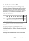

Rev. 1.0, 07/01, page 199 of 372
14.4.4 Serial Data Reception
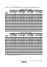
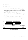
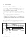
Figure 14-7 shows an example of operation for reception in asynchronous mode. In serial
reception, the SCI operates as described below.
1. The SCI monitors the communication line. If a start bit is detected, the SCI performs internal
synchronization, receives receive data in RSR, and checks the parity bit and stop bit.
2. If an overrun error occurs (when reception of the next data is completed while the RDRF flag
is still set to 1), the OER bit in SSR is set to 1. If the RIE bit in SCR3 is set to 1 at this time, an
ERI interrupt request is generated. Receive data is not transferred to RDR.
3. If a parity error is detected, the PER bit in SSR is set to 1 and receive data is transferred to
RDR. If the RIE bit in SCR3 is set to 1 at this time, an ERI interrupt request is generated.
4. If a framing error is detected (when the stop bit is 0), the FER bit in SSR is set to 1 and receive
data is transferred to RDR. If the RIE bit in SCR3 is set to 1 at this time, an ERI interrupt
request is generated.
5. If reception is completed successfully, the RDRF bit in SSR is set to 1, and receive data is
transferred to RDR. If the RIE bit in SCR3 is set to 1 at this time, an RXI interrupt request is
generated. Continuous reception is possible because the RXI interrupt routine reads the receive
data transferred to RDR before reception of the next receive data has been completed.
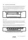
1 frame
Start
bit
Start
bit
Receive
data
Receive
data
Parity
bit
Stop
bit
Parity
bit
Stop
bit
Mark state
(idle state)
1 frame
01 D0 D1 D7 0/1 1 0 10 D0 D1 D7 0/1
Serial
data
RDRF
FER
LSI
operation
User
processing
RDRF
cleared to 0
RDR data read Framing error
processing
RXI request 0 stop bit
detected
ERI request in
response to
framing error
Figure 14-7 Example of SCI Reception in Asynchronous Mode
(8-Bit Data, Parity, One Stop Bit)