


Rev. 1.0, 07/01, page 267 of 372
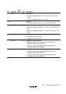
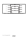
Bit Bit Name
Initial
Value R/W Description
7 LVDE 0 R/W LVD Enable
0: The low-voltage detection circuit is not used. (In standby
mode)
1: The low-voltage detection circuit is used.
6 to 4 − 1 − Reserved
These bits are always read as 1, and cannot be modified.
3 LVDSEL 0 R/W LVDI Detection Level Select
0: When the voltage falls below 3.6 V (typ.) or rises above 3.9 V
(typ.)
1: When the voltage falls below 3.2 V (typ.) or rises above 3.5 V
(typ.)
2 LVDRE 0 R/W LVDR Enable
0: Disables the LVDR function
1: Enables the LVDR function
1 LVDDE 0 R/W Voltage-Fall-Interrupt Enable
0: Interrupt on the power-supply voltage falling below the
selected detection level enabled
1: Interrupt on the power-supply voltage falling below the
selected detection level disabled
0 LVDUE 0 R/W Voltage-Rise-Interrupt Enable
0: Interrupt on the power-supply voltage rising above the
selected detection level enabled
1: Interrupt on the power-supply voltage rising above the
selected detection level disabled