


Rev. 1.0, 07/01, page 65 of 372
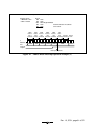
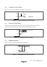
5.1.2 Connecting a Ceramic Oscillator
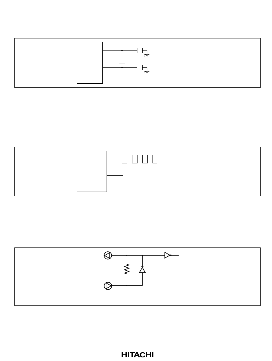
Figure 5-5 shows a typical method of connecting a ceramic oscillator.
OSC
1
OSC
2
C
1
C
2
C
1
= 30 pF ±10%
C
2
= 30 pF ±10%
Figure 5-5 Typical Connection to Ceramic Oscillator
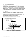
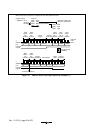
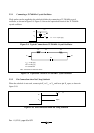
5.1.3 External Clock Input Method
Connect an external clock signal to pin OSC
1
, and leave pin OSC
2
open. Figure 5-6 shows a
typical connection. The duty cycle of the external clock signal must be 45 to 55%.
OSC
1
External clock input
OSC
2
Open
Figure 5-6 Example of External Clock Input
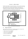
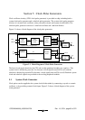
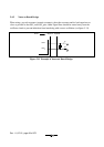
5.2 Subclock Generator
Figure 5-7 shows a block diagram of the subclock generator.
Note : Capacitance is a reference value.
2
1
x
x
Figure 5-7 Block Diagram of the Subclock Generator