


Rev. 1.0, 07/01, page 170 of 372
12.5 Operation Timing
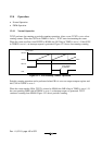
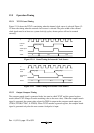
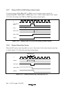
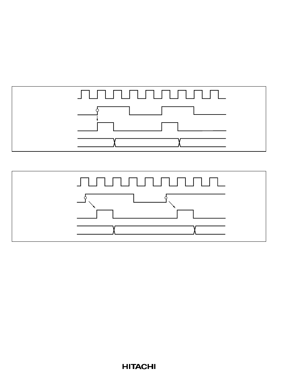
12.5.1 TCNT Count Timing
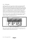
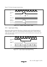
Figure 12-14 shows the TCNT count timing when the internal clock source is selected. Figure 12-
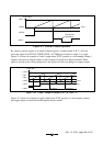
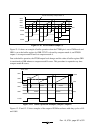
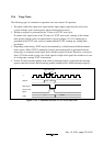
15 shows the timing when the external clock source is selected. The pulse width of the external
clock signal must be at least two system clock (φ) cycles; shorter pulses will not be counted
correctly.
TCNT
TCNT input
clock
Internal
clock
φ
N N+1 N+2
Rising edge
Figure 12-14 Count Timing for Internal Clock Source
TCNT
TCNT input
clock
External
clock
φ
N N+1 N+2
Rising edge Rising edge
Figure 12-15 Count Timing for External Clock Source
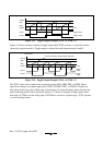
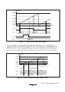
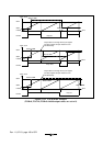
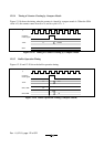
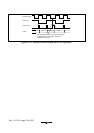
12.5.2 Output Compare Timing
The compare match signal is generated in the last state in which TCNT and the general register
match (when TCNT changes from the matching value to the next value). When the compare match
signal is generated, the output value selected in TIOR is output at the compare match output pin
(FTIOA, FTIOB, FTIOC, or FTIOD). When TCNT matches a general register, the compare match
signal is generated only after the next counter clock pulse is input.