


Rev. 1.0, 07/01, page 180 of 372
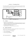
13.3 Operation
The watchdog timer is provided with an 8-bit counter. If 1 is written to WDON while writing 0 to
B2WI when TCSRWE in TCSRWD is set to 1, TCWD begins counting up. (To operate the
watchdog timer, two write accesses to TCSRWD is required.) When a clock pulse is input after
the TCWD count value has reached H'FF, the watchdog timer overflows and an internal reset
signal is generated one base clock (φ) cycle later. The internal reset signal is output for a period of
512 φ
osc
clock cycles. TCWD is a writable counter, and when a value is set in TCWD, the count-
up starts from that value. An overflow period in the range of 1 to 256 input clock cycles can
therefore be set, according to the TCWD set value.
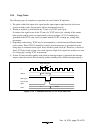
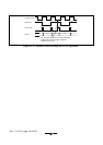
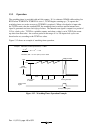
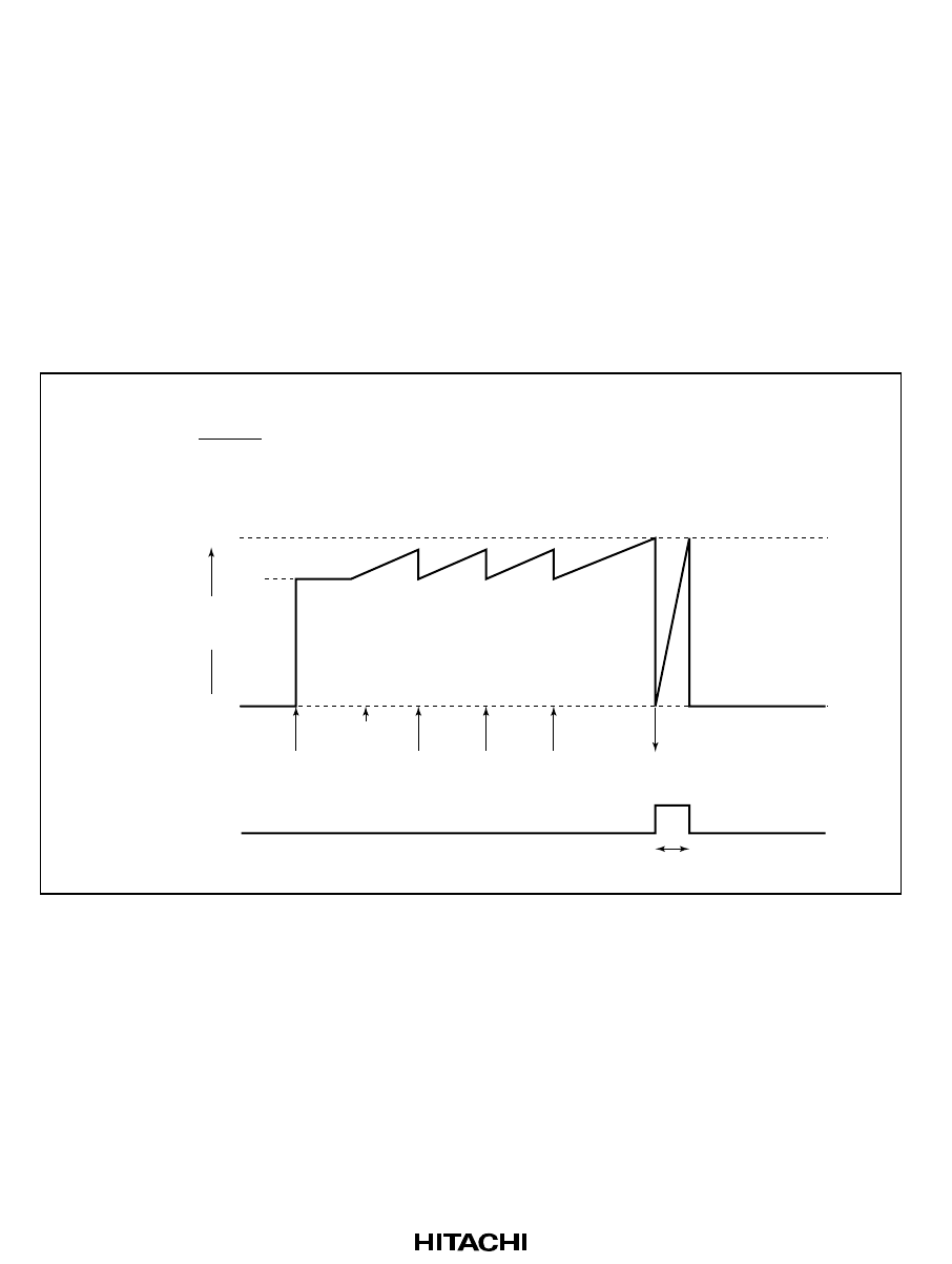
Figure 13-2 shows an example of watchdog timer operation.
Example: With 30ms overflow period when φ = 4 MHz
4 × 10
6
× 30 × 10
–3
= 14.6
8192
TCWD overflow
H'FF
H'00
Internal reset
signal
H'F1
TCWD
count value
H'F1 written
to TCWD
H'F1 written to TCWD Reset generated
Start
512 φ
osc
clock cycles
Therefore, 256 – 15 = 241 (H'F1) is set in TCW.
Figure 13-2 Watchdog Timer Operation Example