


Rev. 1.0, 07/01, page 52 of 372
3.4.3
Interrupt Handling Sequence
Interrupts are controlled by an interrupt controller.
Interrupt operation is described as follows.
1. If an interrupt occurs while the NMI or interrupt enable bit is set to 1, an interrupt request
signal is sent to the interrupt controller.
2. When multiple interrupt requests are generated, the interrupt controller requests to the CPU for
the interrupt handling with the highest priority at that time according to table 3.1. Other
interrupt requests are held pending.
3. The CPU accepts the NMI and address break without depending on the I bit value. Other
interrupt requests are accepted, if the I bit is cleared to 0 in CCR; if the I bit is set to 1, the
interrupt request is held pending.
4. If the CPU accepts the interrupt after processing of the current instruction is completed,
interrupt exception handling will begin. First, both PC and CCR are pushed onto the stack. The
state of the stack at this time is shown in figure 3-2. The PC value pushed onto the stack is the
address of the first instruction to be executed upon return from interrupt handling.
5. Then, the I bit of CCR is set to 1, masking further interrupts excluding the NMI and address
break. Upon return from interrupt handling, the values of I bit and other bits in CCR will be
restored and returned to the values prior to the start of interrupt exception handling.
6.
Next, the CPU generates the vector address corresponding to the accepted interrupt, and
transfers the address to PC as a start address of the interrupt handling-routine. Then a program
starts executing from the address indicated in PC.
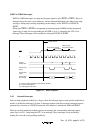
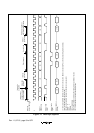
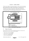
Figure 3-3 shows a typical interrupt sequence where the program area is in the on-chip ROM and
the stack area is in the on-chip RAM.