


Rev. 1.0, 07/01, page 53 of 372
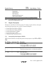
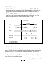
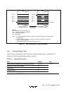
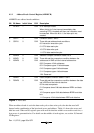
PC and CCR
saved to stack
SP (R7)
SP – 1
SP – 2
SP – 3
SP – 4
Stack area
SP + 4
SP + 3
SP + 2
SP + 1
SP (R7)
Even address
Prior to start of interrupt
exception handling
After completion of interrupt
exception handling
Legend:
PC
H
:
PC
L
:
CCR:
SP:
Upper 8 bits of program counter (PC)
Lower 8 bits of program counter (PC)
Condition code register
Stack pointer
Notes:
CCR
CCR
*3
PCH
PCL
1.
2.
PC shows the address of the first instruction to be executed upon return from the interrupt
handling routine.
Register contents must always be saved and restored by word length, starting from
an even-numbered address.
3. Ignored when returning from the interrupt handling routine.
Figure 3-2 Stack Status after Exception Handling
3.4.4 Interrupt Response Time
Table 3-2 shows the number of wait states after an interrupt request flag is set until the first
instruction of the interrupt handling-routine is executed.
Table 3-2 Interrupt Wait States
Item States Total
Waiting time for completion of executing instruction
*
1 to 13 15 to 27
Saving of PC and CCR to stack 4
Vector fetch 2
Instruction fetch 4
Internal processing 4
Note:
*
Not including EEPMOV instruction.