


Rev. 1.0, 07/01, page 187 of 372
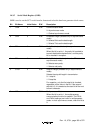
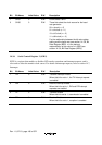
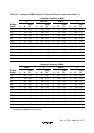
Bit Bit Name Initial Value R/W Description
3 MPIE 0 R/W Multiprocessor Interrupt Enable (enabled only
when the MP bit in SMR is 1 in asynchronous
mode)
When this bit is set to 1, receive data in which the
multiprocessor bit is 0 is skipped, and setting of
the RDRF, FER, and OER status flags in SSR is
disabled. On receiving data in which the
multiprocessor bit is 1, this bit is automatically
cleared and normal reception is resumed. For
details, refer to section 14.6, Multiprocessor
Communication Function.
2 TEIE 0 R/W Transmit End Interrupt Enable
When this bit is set to 1, TEI interrupt request is
enabled.
1
0
CKE1
CKE0
0
0
R/W
R/W
Clock Enable 0 and 1
Selects the clock source.
•
Asynchronous mode
00: On-chip baud rate generator
01: On-chip baud rate generator
Outputs a clock of the same frequency as the
bit rate from the SCK3pin.
10: External clock
Inputs a clock with a frequency 16 times the
bit rate from the SCK3 pin.
11:Reserved
•
Clocked synchronous mode
00: On-chip clock (SCK3 pin functions as clock
output)
01:Reserved
10: External clock (SCK3 pin functions as clock
input)
11:Reserved