


Rev. 1.0, 07/01, page 114 of 372
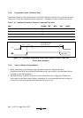
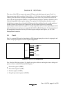
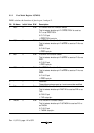
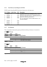
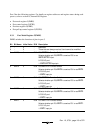
9.1.4 Port Pull-Up Control Register 1(PUCR1)
PUCR1 controls the pull-up MOS in bit units of the pins set as the input ports.
Bit Bit Name Initial Value R/W Description
7
6
5
4
3
2
1
0
PUCR17
PUCR16
PUCR15
PUCR14
−
PUCR12
PUCR11
PUCR10
0
0
0
0
1
0
0
0
R/W
R/W
R/W
R/W
−
R/W
R/W
R/W
Only bits for which PCR1 is cleared are valid. The pull-up
MOS of P17 to P14 and P12 to P10 pins enter the on-
state when these bits are set to 1, while they enter the off-
state when these bits are cleared to 0.
Bit 3 is a reserved bit. This bit is always read as 1 and
cannot be modified.
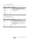
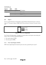
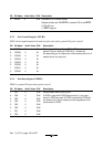
9.1.5 Pin Functions
The correspondence between the register specification and the port functions is shown below.
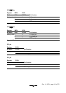
P17/IRQ3/TRGV pin
Register PMR1 PCR1
Bit Name IRQ3 PCR17 Pin Function
Setting value 0 0 P17 input pin
0 1 P17 output pin
1XIRQ3 input/TRGV input pin
Legend X: Don't care.
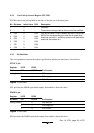
P16/IRQ2 pin
Register PMR1 PCR1
Bit Name IRQ2 PCR16 Pin Function
Setting value 0 0 P16 input pin
0 1 P16 output pin
1XIRQ2 input pin
Legend X: Don't care.