


Rev. 1.0, 07/01, page 369 of 372
Index
A/D Converter ........................................ 253
sample-and-hold circuit ......................260
Scan Mode .......................................... 259
Single Mode........................................ 259
Absolute Maximum Ratings ................... 285
Address Break........................................... 57
Addressing Modes .................................... 28
Absolute Address..................................29
Immediate ............................................. 29
Memory Indirect................................... 30
Program-Counter Relative .................... 30
Register Direct......................................28
Register Indirect.................................... 28
Register Indirect with Displacement..... 29
Register indirect with post-increment...29
Register indirect with pre-decrement....29
Clock
Clock Pulse Generators......................... 63
Subclock Generator...............................65
System Clock Generator....................... 63
Condition-Code Register (CCR)............... 12
CPU ............................................................ 7
Effective Address......................................30
Electrical Characteristics (F-ZTAT™
Version................................................ 285
AC Characteristics.............................. 293
DC Characteristics.............................. 287
Electrical Characteristics (Mask ROM
Version) ..............................................302
AC Characteristics.............................. 309
DC Characteristics.............................. 303
Exception Handling .................................. 43
Reset ..................................................... 43
Trap Instruction.....................................43
flash memory ............................................ 81
Auto-Erase Mode................................ 102
Auto-Program Mode........................... 100
Boot Mode ............................................86
boot program.........................................86
Erase/Erase-Verify................................92
Error Protection.....................................95
Hardware Protection..............................95
Memory Read Mode .............................98
Power-Down State ..............................107
Program/Program-Verify ......................90
Programmer Mode ................................96
Socket Adapter......................................96
Software Protection...............................95
Status Polling ......................................105
Status Read Mode ...............................104
General Registers......................................11
I/O Ports..................................................111
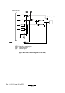
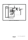
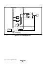
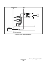
I/O Port Block Diagrams.....................349
I
2
C Bus Data Format...............................234
I
2
C Bus Interface 2 (IIC2).......................221
acknowledge........................................234
Bit Synchronous Circuit......................251
Clock Synchronous Serial Format.......243
general call address .............................232
Noise Canceler....................................245
Slave address.......................................234
Start condition.....................................234
Stop condition .....................................235
Transfer Rate.......................................225
Instruction Set ...........................................17
Internal Power Supply Step-Down Circuit
............................................................273
Interrupt
Internal Interrupts..................................51
Interrupt Response Time.......................53
IRQ3 to IRQ0 Interrupts .......................50
NMI Interrupt........................................50
WKP5 to WKP0 Interrupts ...................51
interrupt mask bit (I) .................................12