


Rev. 1.0, 07/01, page 148 of 372
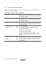
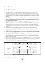
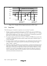
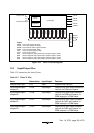
Counter cleared
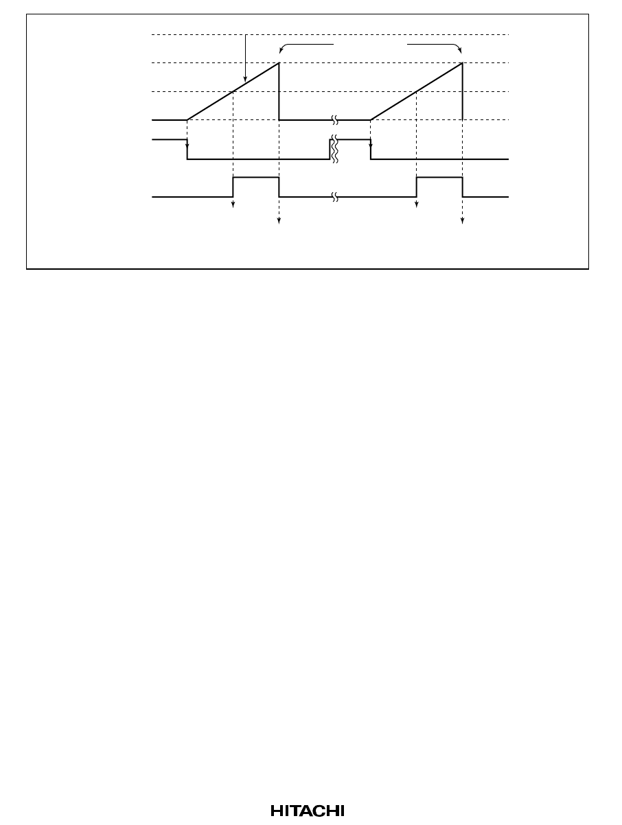
TCNTV
H'FF
TCORA
TCORB
H'00
TRGV
TMOV
Compare match A
Compare match B
clears TCNTV and
halts count-up
Compare match B
clears TCNTV and
halts count-up
Compare match A
Figure 11-10 Example of Pulse Output Synchronized to TRGV Input
11.6 Usage Notes
The following types of contention or operation can occur in timer V operation.
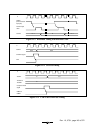
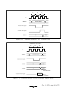
1.
Writing to registers is performed in the T3 state of a TCNTV write cycle. If a TCNTV clear
signal is generated in the T3 state of a TCNTV write cycle, as shown in figure 11-11, clearing
takes precedence and the write to the counter is not carried out. If counting-up is generated in
the T3 state of a TCNTV write cycle, writing takes precedence.
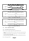
2.
If a compare match is generated in the T3 state of a TCORA or TCORB write cycle, the write
to TCORA or TCORB takes precedence and the compare match signal is inhibited. Figure 11-
12 shows the timing.
3.
If compare matches A and B occur simultaneously, any conflict between the output selections
for compare match A and compare match B is resolved by the following priority: toggle
output > output 1 > output 0.
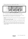
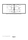
4.
Depending on the timing, TCNTV may be incremented by a switch between different internal
clock sources. When TCNTV is internally clocked, an increment pulse is generated from the
falling edge of an internal clock signal, that is divided system clock (φ). Therefore, as shown
in figure 11-3 the switch is from a high clock signal to a low clock signal, the switchover is
seen as a falling edge, causing TCNTV to increment. TCNTV can also be incremented by a
switch between internal and external clocks.