


Rev. 1.0, 07/01, page 185 of 372
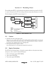
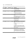
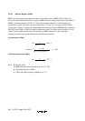
14.3.5 Serial Mode Register (SMR)
SMR is used to set the SCI’s serial transfer format and select the baud rate generator clock source.
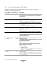
Bit Bit Name Initial Value R/W Description
7 COM 0 R/W Communication Mode
0: Asynchronous mode
1: Clocked synchronous mode
6 CHR 0 R/W Character Length (enabled only in asynchronous
mode)
0: Selects 8 bits as the data length.
1: Selects 7 bits as the data length.
5 PE 0 R/W Parity Enable (enabled only in asynchronous
mode)
When this bit is set to 1, the parity bit is added to
transmit data before transmission, and the parity
bit is checked in reception.
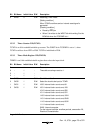
4 PM 0 R/W Parity Mode (enabled only when the PE bit is 1 in
asynchronous mode)
0: Selects even parity.
1: Selects odd parity.
3 STOP 0 R/W Stop Bit Length (enabled only in asynchronous
mode)
Selects the stop bit length in transmission.
0: 1 stop bit
1: 2 stop bits
For reception, only the first stop bit is checked,
regardless of the value in the bit. If the second
stop bit is 0, it is treated as the start bit of the next
transmit character.
2 MP 0 R/W Multiprocessor Mode
When this bit is set to 1, the multiprocessor
communication function is enabled. The PE bit
and PM bit settings are invalid in multiprocessor
mode. In clock synchronous mode, clear this bit to
0.