


Rev. 1.0, 07/01, page 138 of 372
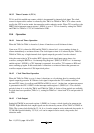
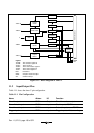
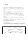
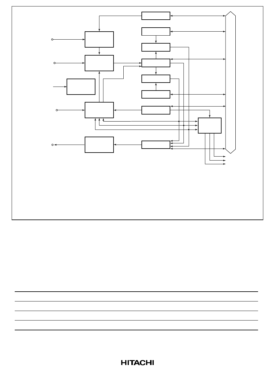
TRGV
TMCIV
TMRIV
TMOV
ø
Trigger
control
Clock select
Clear
control
Output
control
PSS
TCRV1
TCORB
Comparator
TCNTV
Comparator
TCORA
TCRV0
Interrupt
request
control
TCSRV
CMIA
CMIB
OVI
Internal data bus
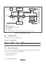
Legend:
TCORA: Time constant register A
TCORB: Time constant register B
TCNTV: Timer counter V
TCSRV: Timer control/status register V
TCRV0: Timer control register V0
TCRV1: Timer control register V1
PSS: Prescaler S
CMIA: Compare-match interrupt A
CMIB: Compare-match interrupt B
OVI: Overflow interupt
Figure 11-1 Block Diagram of Timer V
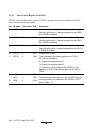
11.2 Input/Output Pins
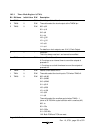
Table 11-1 shows the timer V pin configuration.
Table 11-1 Pin Configuration
Name
Abbrev.
I/O
Function
Timer V output
TMOV
Output
Timer V waveform output
Timer V clock input
TMCIV
Input
Clock input to TCNTV
Timer V reset input
TMRIV
Input
External input to reset TCNTV
Trigger input
TRGV
Input
Trigger input to initiate counting