


Rev. 1.0, 07/01, page 156 of 372
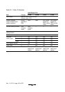
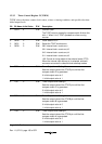
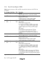
12.3.2 Timer Control Register W(TCRW)
TCRW selects the timer counter clock source, selects a clearing condition, and specifies the timer
initial output levels.
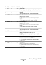
Bit Bit Name Initial Value R/W Description
7 CCLR 0 R/W Counter Clear
The TCNT value is cleared by compare match A when this
bit is 1. When it is 0, TCNT operates as a free-running
counter.
6
5
4
CKS2
CKS1
CKS0
0
0
0
R/W
R/W
R/W
Clock Select 2 to 0
Select the TCNT clock source.
000: Internal clock: counts on φ
001: Internal clock: counts on φ/2
010: Internal clock: counts on φ/4
011: Internal clock: counts on φ/8
1XX: Counts on rising edges of the external event (FTCI)
When the internal clock source (φ) is selected, subclock
sources are counted in subactive and subsleep modes.
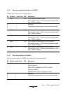
3 TOD 0 R/W Timer Output Level Setting D
Sets the output value of the FTIOD pin until the first
compare match D is generated.
0: Initial output value is 0
1: Initial output value is 1
2 TOC 0 R/W Timer Output Level Setting C
Sets the output value of the FTIOC pin until the first
compare match C is generated.
0: Initial output value is 0
1: Initial output value is 1
1 TOB 0 R/W Timer Output Level Setting B
Sets the output value of the FTIOB pin until the first
compare match B is generated.
0: Initial output value is 0
1: Initial output value is 1
0 TOA 0 R/W Timer Output Level Setting A
Sets the output value of the FTIOA pin until the first
compare match A is generated.
0: Initial output value is 0
1: Initial output value is 1
Legend X: Don't care.