


Rev. 1.0, 07/01, Page
xxiii
of
xxiv
Section 16 A/D Converter
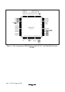
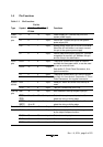
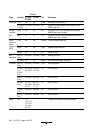
Table 16-1 Pin Configuration..................................................................................................255
Table 16-2 Analog Input Channels and Corresponding ADDR Registers ..............................256
Table 16-3 A/D Conversion Time (Single Mode)...................................................................261
Section 20 Electrical Characteristics
Table 20-1 Absolute Maximum Ratings .................................................................................285
Table 20-2 DC Characteristics (1)...........................................................................................287
Table 20-2 DC Characteristics (2)...........................................................................................292
Table 20-3 AC Characteristics ................................................................................................293
Table 20-4 I
2
C Bus Interface Timing......................................................................................295
Table 20-5 Serial Interface (SCI) Timing................................................................................296
Table 20-6 A/D Converter Characteristics..............................................................................297
Table 20-7 Watchdog Timer Characteristics...........................................................................298
Table 20-8 Flash Memory Characteristics...............................................................................299
Table 20-9 Power-Supply-Voltage Detection Circuit Characteristics.....................................301
Table 20-10 DC Characteristics (1)...........................................................................................303
Table 20-10 DC Characteristics (2)...........................................................................................308
Table 20-11 AC Characteristics ................................................................................................309
Table 20-12 I
2
C Bus Interface Timing......................................................................................311
Table 20-13 Serial Interface (SCI) Timing................................................................................312
Table 20-14 A/D Converter Characteristics..............................................................................313
Table 20-15 Watchdog Timer Characteristics...........................................................................314
Table 20-16 Power-Supply-Voltage Detection Circuit Characteristics.....................................315
Appendix
Table A.1 Instruction Set .......................................................................................................321
Table A.2 Operation Code Map (1).......................................................................................334
Table A.2 Operation Code Map (2).......................................................................................335
Table A.2 Operation Code Map (3).......................................................................................336
Table A.3 Number of Cycles in Each Instruction..................................................................338
Table A.4 Number of Cycles in Each Instruction..................................................................339
Table A.5 Combinations of Instructions and Addressing Modes ..........................................348