


Rev. 1.0, 07/01, page 246 of 372
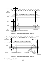
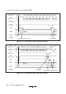
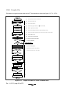
15.4.8 Example of Use
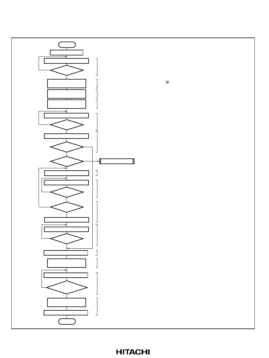
Flowcharts in respective modes that use the I
2
C bus interface are shown in figures 15-17 to 15-20.
BBSY=0 ?
No
TEND=1 ?
No
Yes
Start
[1]
[2]
[3]
[4]
[5]
[6]
[7]
[8]
[9]
[10]
[11]
[12]
[13]
[14]
Initialize
Set MST and TRS
in ICCR1 to 1.
Write 1 to BBSY
and 0 to SCP.
Write transmit data
in ICDRT
Write 0 to BBSY
and SCP
Set MST to 1 and TRS
to 0 in ICCR1
Read BBSY in ICCR2
Read TEND in ICSR
Read ACKBR in ICIER
Mater receive mode
Yes
ACKBR=0 ?
Write transmit data in ICDRT
Read TDRE in ICSR
Read TEND in ICSR
Clear TEND in ICSR
Read STOP in ICSR
Clear TDRE in ICSR
End
Write transmit data in ICDRT
Transmit
mode?
No
Yes
TDRE=1 ?
Last byte?
STOP=1 ?
No
No
No
No
No
Yes
Yes
TEND=1 ?
Yes
Yes
Yes
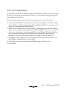
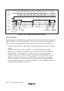
[1] Test the status of the SCL and SDA lines.
[2] Set master transmit mode.
[3] Issue the start condition.
[4] Set the first byte (slave address + R/
) of transmit data.
[5] Wait for 1 byte to be transmitted.
[6] Test the acknowledge transferred from the specified slave device.
[7] Set the second and subsequent bytes (except for the final byte) of transmit data.
[8] Wait for ICDRT empty.
[9] Set the last byte of transmit data.
[10] Wait for last byte to be transmitted.
[11] Clear the TEND flag.
[12] Issue the stop condition.
[13] Wait for the creation of stop condition.
[14] Set slave receive mode. Clear TDRE.
Figure 15-17 Sample Flowchart for Master Transmit Mode