


Rev. 1.0, 07/01, page 30 of 372
The instruction contains 8-bit (#xx:8), 16-bit (#xx:16), or 32-bit (#xx:32) immediate data as an
operand.
The ADDS, SUBS, INC, and DEC instructions contain immediate data implicitly. Some bit
manipulation instructions contain 3-bit immediate data in the instruction code, specifying a bit
number. The TRAPA instruction contains 2-bit immediate data in its instruction code, specifying a
vector address.
Program-Counter Relative—@(d:8, PC) or @(d:16, PC)
This mode is used in the BSR instruction. An 8-bit or 16-bit displacement contained in the
instruction is sign-extended and added to the 24-bit PC contents to generate a branch address. The
PC value to which the displacement is added is the address of the first byte of the next instruction,
so the possible branching range is –126 to +128 bytes (–63 to +64 words) or –32766 to +32768
bytes (–16383 to +16384 words) from the branch instruction. The resulting value should be an
even number.
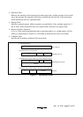
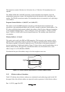
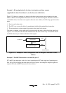
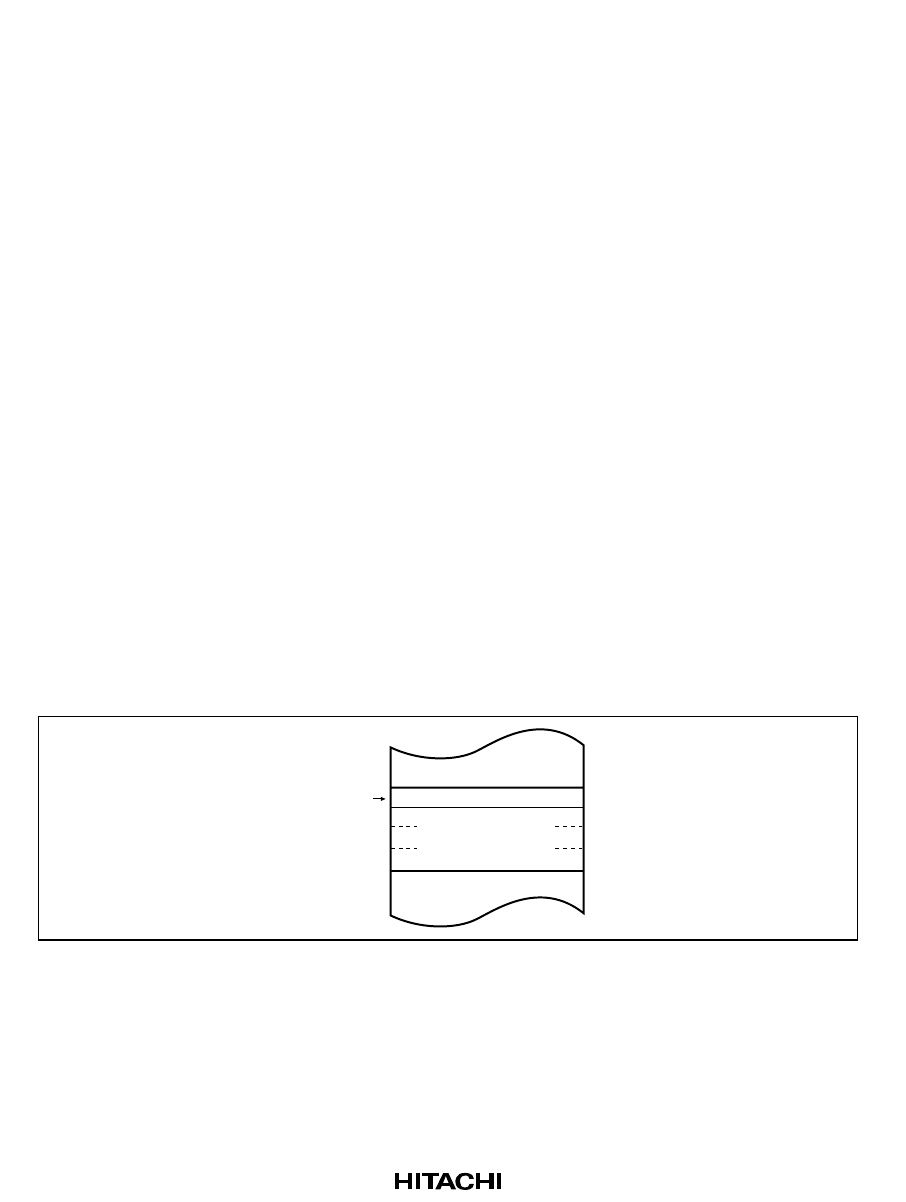
Memory Indirect—@@aa:8
This mode can be used by the JMP and JSR instructions. The instruction code contains an 8-bit
absolute address specifying a memory operand. This memory operand contains a branch address.
The memory operand is accessed by longword access. The first byte of the memory operand is
ignored, generating a 24-bit branch address. Figure 2-8 shows how to specify branch address for in
memory indirect mode. The upper bits of the absolute address are all assumed to be 0, so the
address range is 0 to 255 (H'0000 to H'00FF).
Note that the first part of the address range is also the exception vector area.
Specified
by @aa:8
Branch address
Dummy
Figure 2-8 Branch Address Specification in Memory Indirect Mode
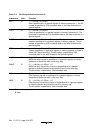
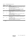
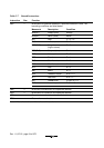
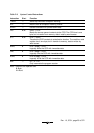
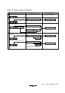
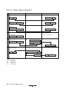
2.5.2 Effective Address Calculation
Table 2-12 indicates how effective addresses are calculated in each addressing mode. In this LSI
the upper 8 bits of the effective address are ignored in order to generate a 16-bit effective address.