


5
UTILITY PACKAGE (GX Configurator-TI)
5.5 Auto Refresh Setting
5 - 17
1
OVERVIEW
2
SYSTEM
CONFIGURATION
3
SPECIFICATIONS
4
PROCEDURES AND
SETTINGS BEFORE
SYSTEM OPERATION
5
UTILITY PACKAGE
(GX CONFIGURATOR-TI)
6
PROGRAMMING
7
ONLINE MODULE
CHANGE
8
TROUBLESHOOTING
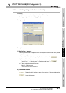
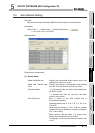
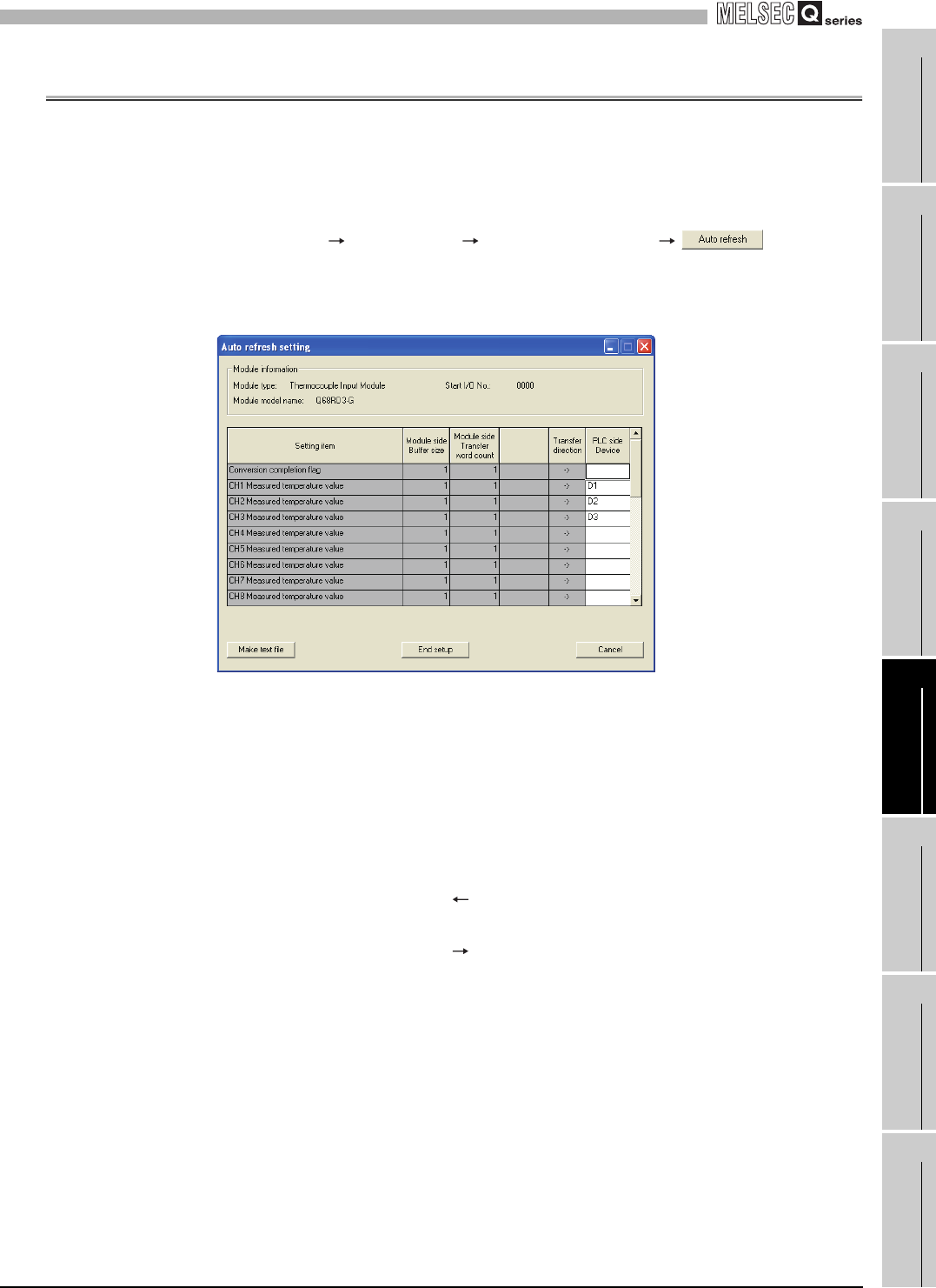
5.5 Auto Refresh Setting
[Purpose]
Sets the automatically refreshed Q68RD3-G buffer memory for each channel.
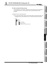
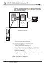
[Procedure]
"Start I/O No.
*1
" "Module type" "Module model name"
* 1 Enter the start I/O No. in hexadecimal.
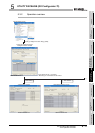
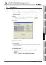
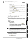
[Setting screen]
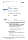
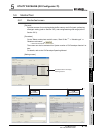
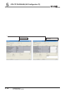
[Description of screen items]
(1) Screen items
Model side Buffer size : Displays the transferable buffer memory size of the
setting item (fixed to one word).
Model side Transfer word
count
: Displays the number of transferable words starting
from the "PLC side Device" (fixed to one word).
Transfer direction :
" " indicates that data are written from the device to
the buffer memory.
" " indicates that data are read from the buffer
memory to the device.
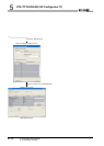
PLC side Device : Enter a device of the CPU module that is
automatically refreshed.
Applicable devices are X, Y, M, L, B, T, C, ST, D, W,
R, and ZR.
When using bit devices X, Y, M, L or B, set a device
number that can be divided by 16 points (examples:
X10, Y120 or M16).
Buffer memory data are stored in a 16-point area,
starting from the specified device number.
For example, if X10 is entered, data are stored in X10
to X1F.