3
SPECIFICATIONS
3.3 I/O Signals for Communicating with Programmable Controller CPU
3.3.2 I/O signal details
3 - 21
1
OVERVIEW
2
SYSTEM
CONFIGURATION
3
SPECIFICATIONS
4
PROCEDURES AND
SETTINGS BEFORE
SYSTEM OPERATION
5
UTILITY PACKAGE
(GX CONFIGURATOR-TI)
6
PROGRAMMING
7
ONLINE MODULE
CHANGE
8
TROUBLESHOOTING
2) Rate alarm
• This signal turns ON when the rate alarm is enabled and the change of
measured temperature value exceeds the preset range of the Rate alarm
upper/lower limit values (Un\G134 to Un\G149) in any of conversion-
enabled channels.
• This signal automatically turns OFF when the change of measured
temperature value returns to within the setting range for all conversion-
enabled channels. The "ALM" LED also turns off.
(7) Conversion completion flag (XE)
(a) This flag turns ON when measured temperature values of all conversion-enabled
channels are stored into the buffer memory after the programmable controller is
powered ON or the reset operation of the CPU module is performed.
(b) When averaging processing is specified, this signal also turns ON when the
converted measured temperature values are stored into the buffer memory after
completion of averaging processing.
(c) Status of this flag depends on the ON/OFF status of Operating condition setting
completion flag (X9).
1) When Operating condition setting completion flag (X9) turns ON (stop
conversion)
• Temperature conversion for conversion-enabled channels is started.
• After the measured temperature value is stored into the buffer memory,
the bit of corresponding channel in the Conversion completion flag
(Un\G10) turns ON (changes to "1").
• After the measured temperature values of all conversion-enabled
channels are stored into the buffer memory, this flag turns ON.
2) When Operating condition setting completion flag (X9) turns OFF (conversion
stop)
• The bits of all channels in the Conversion completion flag (Un\G10) are
turned OFF (changes to "0").
• This flag turns OFF.
Note that even though conversion has been stopped, the data
immediately before the stop are held in the Measured temperature values
stored in the buffer memory.
(d) Use this signal or the Conversion completion flag (Un\G10) as an interlock to read
out the measured temperature value.
(e) This flag does not turn ON when all channels are set to conversion-disabled.
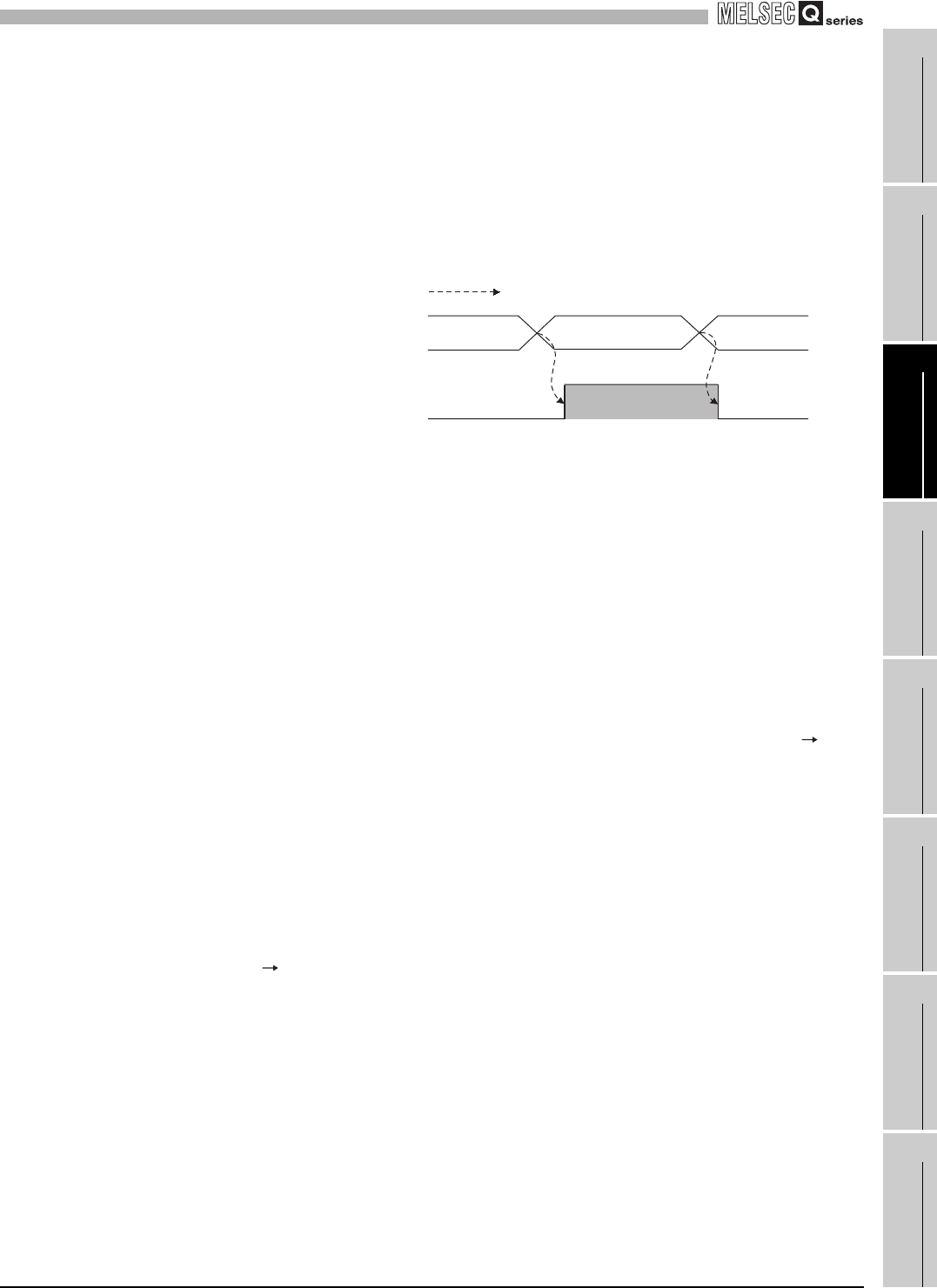
Executed in Q68RD3-G
Warning output flag
(Un\G47, Un\G48)
Warning output
signal (XD)
0
0
Warning occurrence
(process alarm, rate alarm)


