


3
SPECIFICATIONS
3.4 Buffer Memory
3.4.14 Disconnection detection flag (Un\G49)
3 - 39
1
OVERVIEW
2
SYSTEM
CONFIGURATION
3
SPECIFICATIONS
4
PROCEDURES AND
SETTINGS BEFORE
SYSTEM OPERATION
5
UTILITY PACKAGE
(GX CONFIGURATOR-TI)
6
PROGRAMMING
7
ONLINE MODULE
CHANGE
8
TROUBLESHOOTING
3.4.14 Disconnection detection flag (Un\G49)
(1) The flag of the corresponding channel turns ON (changes to "1") when
the disconnection state of RTD is detected.
(2) Disconnection detection is executed on conversion-enabled channels
only.
(3) Disconnection state is detectable for each channel.
(4) If disconnection is detected on any of conversion-enabled channels,
Disconnection detection signal (XC) also turns ON.
For a channel where disconnection is detected, a value based on the
Conversion setting for disconnection detection (Un\G164 and Un\G165)
is stored in the CH Measured temperature value (Un\G11 to Un\G18).
Conversion for the channels not disconnected is continued.
(5) When Operating condition setting request (Y9) or Error clear request
(YF) is turned ON, this flag will be cleared.
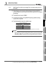
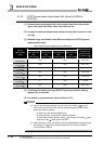
(6) The following table shows the relationship between the Disconnection
detection flag and conversion enable/disable setting.
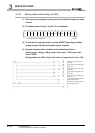
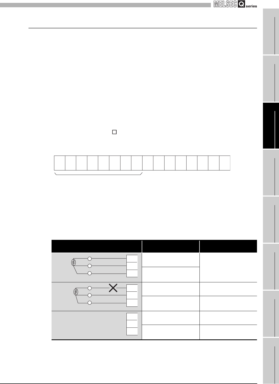
Table 3.13 Relationship between the Disconnection detection flag and conversion enable/disable setting
Connection status
Conversion enable/disable
setting
Disconnection detection
flag
Enable
OFF
Disable
Enable ON
Disable OFF
Enable ON
Disable OFF
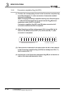
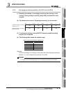
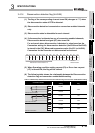
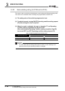
b15 b14 b13 b12 b11 b10 b9 b8 b7 b6 b5 b4 b3 b2 b1 b0
CH8 CH7 CH6 CH5 CH4 CH3 CH2 CH100000000
0: Normal
1: Disconnected
Data for b8 to b15 is fixed to "0".
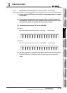
A
B
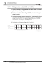
b
Without disconnection
A
B
b
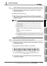
With disconnection
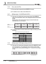
A
B
b
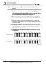
Without connection