


3 - 22
3.3 I/O Signals for Communicating with Programmable Controller CPU
3.3.2 I/O signal details
3
SPECIFICATIONS
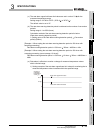
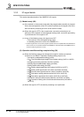
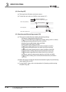
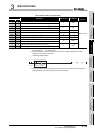
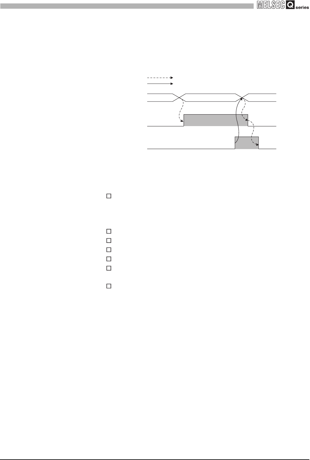
(8) Error flag (XF)
(a) This signal turns ON when a write error occurs.
(b) To clear the error code, turn ON Error clear request (YF).
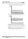
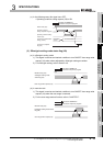
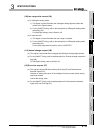
(9) Operating condition setting request (Y9)
(a) This signal is turned ON when enabling the following settings.
• Conversion enable/disable setting (Un\G0)
• CH Time/Count/Moving average/Time constant setting (Un\G1 to Un\G8)
• Averaging processing selection (Un\G24, Un\G25)
• Warning output enable/disable setting (Un\G46)
• Scaling valid/invalid setting (Un\G58)
• CH Scaling range upper/lower limit values (Un\G62 to Un\G77)
• CH Scaling width upper/lower limit values (Un\G78 to Un\G93)
• CH Process alarm upper/lower limit values (Un\G94 to Un\G125)
• CH Rate alarm warning detection period (Un\G126 to Un\G133)
• CH Rate alarm upper/lower limit values (Un\G134 to Un\G149)
• Conversion setting for disconnection detection (Un\G164, Un\G165)
• CH Conversion setting value for disconnection detection (Un\G166 to
Un\G173)
(b) When this signal is turned ON, Disconnection detection signal (XC) and Warning
output signal (XD) turn OFF.
(c) For the ON/OFF timing, refer to the description for Operating condition setting
completion flag (X9).
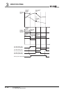
Error code (Un\G19)
Error flag (XF)
Error clear request (YF)
Error occurrence
Executed in Q68RD3-G
Executed in sequence program