4 - 5
4.3 Part Names
4
PROCEDURES AND SETTINGS BEFORE SYSTEM
OPERATION
* 1 For actual wiring, refer to Section 4.4.2 External wiring.
(1) Connector for external wiring
The connectors for use with the Q68RD3-G should be purchased separately by the
user.The following tables show the connector types and the crimp-contact tool.
(a) Connector types
*1
* 1 The A6CON3 (pressure-displacement type, straight out) connector cannot be used for the
Q68RD3-G.
(b) Crimp-contact too
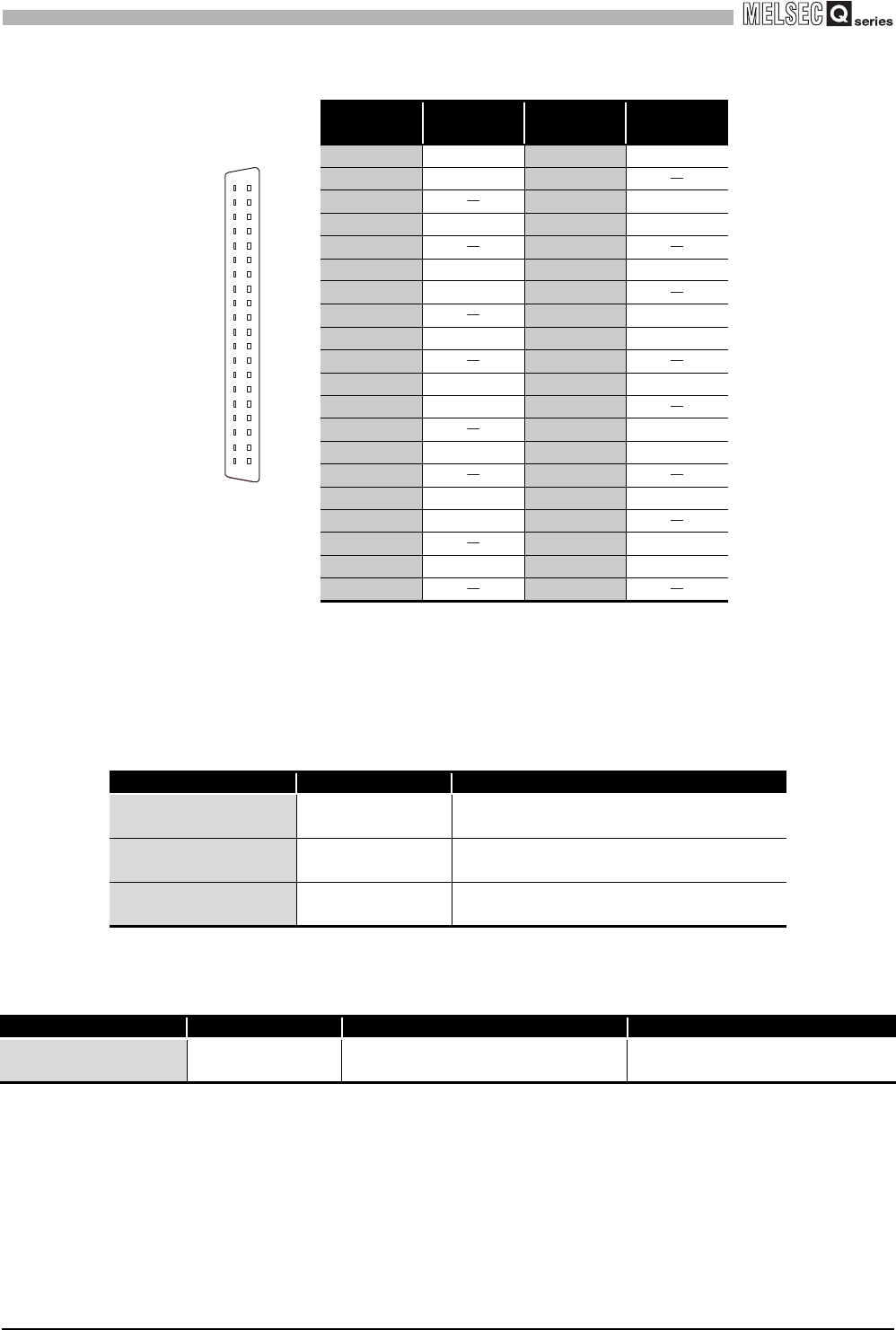
Table 4.3 Signal name
Terminal
number
Signal name
Terminal
number
Signal name
A1 CH1 A1 B1 CH1 B1
A2 CH1 b1 B2
A3 B3 CH2 b2
A4 CH2 A2 B4 CH2 B2
A5 B5
A6 CH3 A3 B6 CH3 B3
A7 CH3 b3 B7
A8 B8 CH4 b4
A9 CH4 A4 B9 CH4 B4
A10 B10
A11 CH5 A5 B11 CH5 B5
A12 CH5 b5 B12
A13 B13 CH6 b6
A14 CH6 A6 B14 CH6 B6
A15 B15
A16 CH7 A7 B16 CH7 B7
A17 CH7 b7 B17
A18 B18 CH8 b8
A19 CH8 A8 B19 CH8 B8
A20 B20
Type Model name Applicable wire size
Soldering type
(straight out)
A6CON1
0.3mm
2
(AWG22) (stranded)
Crimp-contact type
(straight out)
A6CON2
0.088mm
2
to 0.24mm
2
(AWG28 to 24) (stranded)
Soldering type
(straight out/diagonal out)
A6CON4
0.3mm
2
(AWG22) (stranded)
Type Model name Applicable wire size Contact
Crimp-contact tool FCN-363T-T005/H
0.088mm
2
to 0.24mm
2
(AWG28 to 24)
FUJITSU COMPONENT LIMITED
http://www.fcl.fujitsu.com/en/
B20
Seen from the front
of the module
B19
B18
B17
B16
B15
B14
B13
B12
B11
B10
B9
B8
B7
B6
B5
B4
B3
B2
B1
A20
A19
A18
A17
A16
A15
A14
A13
A12
A11
A10
A9
A8
A7
A6
A5
A4
A3
A2
A1


