


4
PROCEDURES AND SETTINGS BEFORE SYSTEM
OPERATION
4.5 Intelligent Function Module Switch Setting
4 - 8
1
OVERVIEW
2
SYSTEM
CONFIGURATION
3
SPECIFICATIONS
4
PROCEDURES AND
SETTINGS BEFORE
SYSTEM OPERATION
5
UTILITY PACKAGE
(GX CONFIGURATOR-TI)
6
PROGRAMMING
7
ONLINE MODULE
CHANGE
8
TROUBLESHOOTING
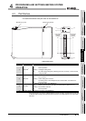
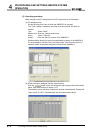
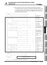
4.5 Intelligent Function Module Switch Setting
The intelligent function module switches are set on the I/O assignment tab of PLC
parameter in GX Developer.
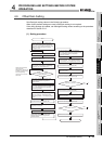
(1) Setting item
There are five intelligent function module switches, Switch 1 to 5. Values are set with
16-bit data.
The default value when not setting the intelligent function module switches is "0" for
all Switch 1 to 5.
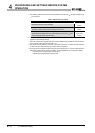
* 1 Setting any value within the setting range will provide the same operation.
When the setting range is 1
H to FH, set "1H" for example.
* 2 Setting a value other than "0
H" results in an error.
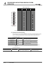
Table 4.4 Intelligent function module switch setting
Setting item
Switch 1
Measurement range
setting
(CH1 to CH4)
RTD Measurement range
Setting
value
New JIS
(Pt100)
-200 to 850
0
H
-20 to 120
1
H
0 to 200
4
H
Old JIS
(JPt100)
-180 to 600
2
H
Switch 2
Measurement range
setting
(CH5 to CH8)
-20 to 120
3
H
0 to 200
5
H
Ni100
-60 to 180
8
H
Setting a value other than above results in a range setting
error (error code: 10 ) and measured temperature is not
converted. ( indicates the error corresponding channel
number.)
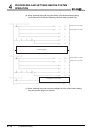
Switch 3
Offset/gain setting
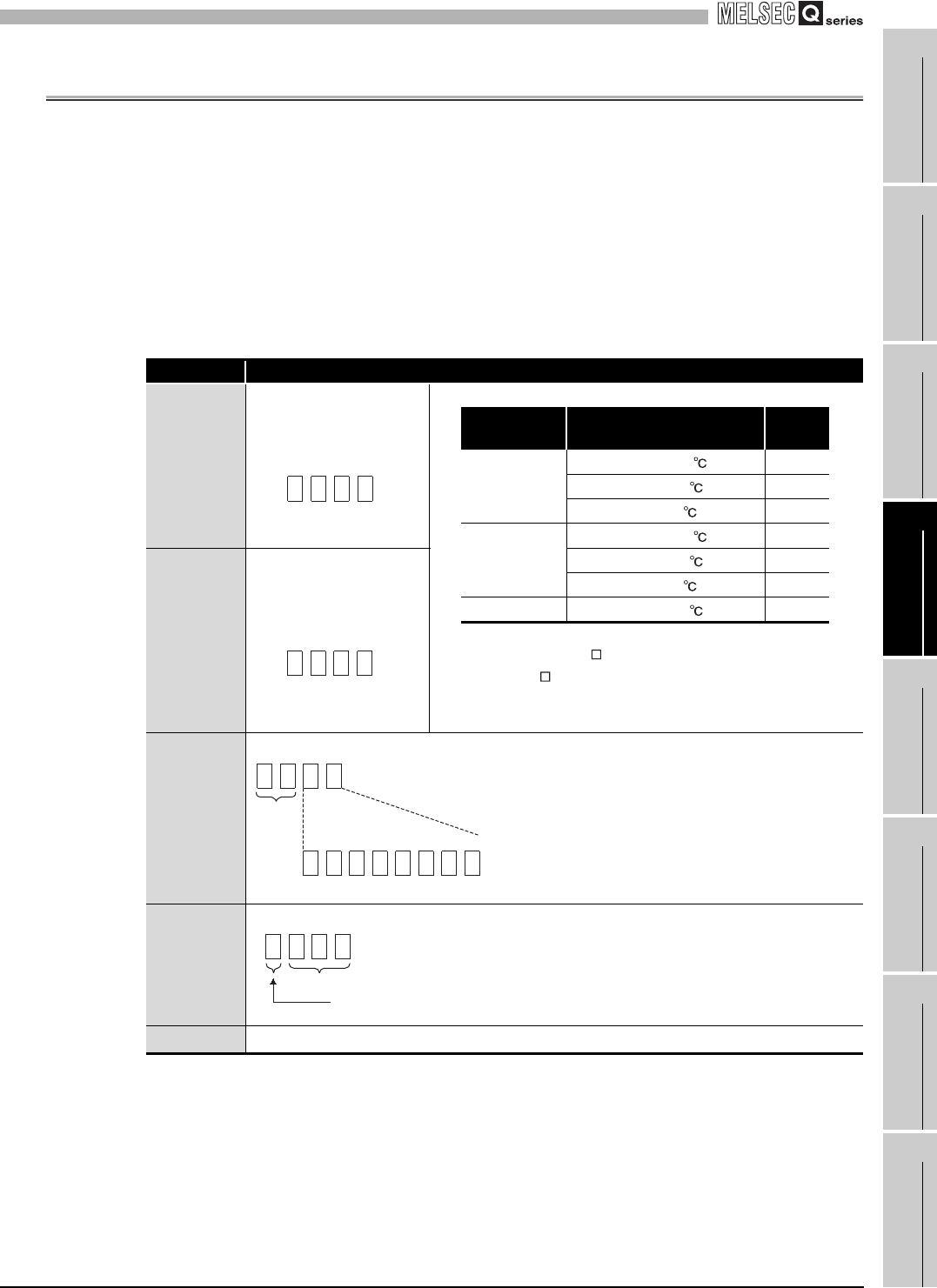
Switch 4
Mode setting
Switch 5
0H : Fixed
*2
CH4CH3 CH2CH1
H
CH8CH7CH6 CH5
H
H
00
b7 b6 b5 b4 b3 b2 b1 b0
CH8 CH7CH6CH5 CH4CH3 CH2CH1
Fixed to 0
H
0: Factory default settin
g
1: User range setting
Fixed to 0
H
0
H
: Normal mode
1
H
to F
H
*1
: Offset/gain setting mode
H
000