


3
SPECIFICATIONS
3.3 I/O Signals for Communicating with Programmable Controller CPU
3.3.1 I/O signal list
3 - 17
1
OVERVIEW
2
SYSTEM
CONFIGURATION
3
SPECIFICATIONS
4
PROCEDURES AND
SETTINGS BEFORE
SYSTEM OPERATION
5
UTILITY PACKAGE
(GX CONFIGURATOR-TI)
6
PROGRAMMING
7
ONLINE MODULE
CHANGE
8
TROUBLESHOOTING
3.3 I/O Signals for Communicating with Programmable Controller
CPU
This section describes the I/O signal assignment and the function of each signal.
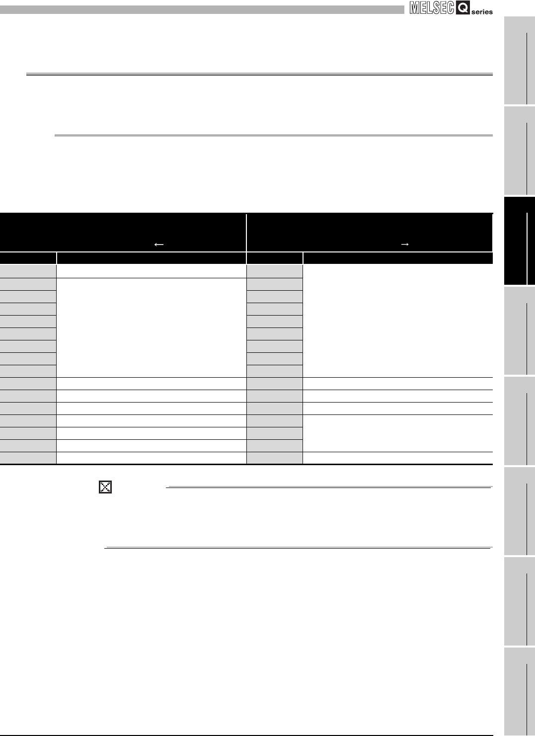
3.3.1 I/O signal list
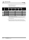
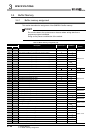
The following table lists the I/O signals of the Q68RD3-G.
The I/O numbers (X/Y) described in this chapter and later indicate the case where the start
I/O number of the Q68RD3-G is set to "0".
POINT
The reserved signals marked *1 are used by the system and are not available for
the user. If they are turned ON/OFF in a sequence program, the functions of those
signals in the Q68RD3-G cannot be guaranteed.
Table 3.8 I/O signal list
Input signal
(Signal direction:
Programmable controller CPU Q68RD3-G)
Output signal
(Signal direction:
Programmable controller CPU Q68RD3-G)
Device No. Signal name Device No. Signal name
X0
Module ready
Y0
Reserved
*1
X1
Reserved
*1
Y1
X2 Y2
X3 Y3
X4 Y4
X5 Y5
X6 Y6
X7 Y7
X8 Y8
X9 Operating condition setting completion flag Y9 Operating condition setting request
XA Offset/gain setting mode status flag YA User range write request
XB Channel change completion flag YB Channel change request
XC Disconnection detection signal YC
Reserved
*1
XD Warning output signal YD
XE Conversion completion flag YE
XF Error flag YF Error clear request