


3
SPECIFICATIONS
3.3 I/O Signals for Communicating with Programmable Controller CPU
3.3.2 I/O signal details
3 - 23
1
OVERVIEW
2
SYSTEM
CONFIGURATION
3
SPECIFICATIONS
4
PROCEDURES AND
SETTINGS BEFORE
SYSTEM OPERATION
5
UTILITY PACKAGE
(GX CONFIGURATOR-TI)
6
PROGRAMMING
7
ONLINE MODULE
CHANGE
8
TROUBLESHOOTING
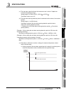
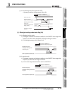
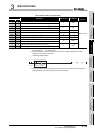
(10)User range write request (YA)
(a) In offset/gain setting mode
1) This signal is turned ON when the offset/gain setting adjusted values are
written to the Flash memory.
2) For the ON/OFF timing, refer to the description for Offset/gain setting mode
status flag (XA).
For offset/gain setting, refer to Section 4.6.
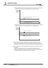
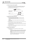
(b) In normal mode
1) This signal is turned ON when the user range is restored.
2) For the ON/OFF timing, refer to the description for Offset/gain setting mode
status flag (XA).
For the user range restore function, refer to CHAPTER 7.
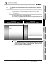
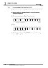
(11)Channel change request (YB)
(a) This signal is turned ON when changing the offset/gain setting target channel.
(b) For the ON/OFF timing, refer to the description for Channel change completion
flag (XB).
For offset/gain setting, refer to Section 4.6.
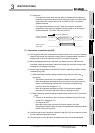
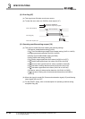
(12)Error clear request (YF)
(a) This signal is turned ON when clearing Error flag (XF) and Disconnection
detection signal (XC).
However, a setting value error of the intelligent function module switch setting
cannot be cleared.
Correct the setting value.
(b) For the ON/OFF timing, refer to the descriptions for Disconnection detection
signal (XC) and Error flag (XF).