


4
PROCEDURES AND SETTINGS BEFORE SYSTEM
OPERATION
4.4 Wiring
4.4.1 Wiring precautions
4 - 6
1
OVERVIEW
2
SYSTEM
CONFIGURATION
3
SPECIFICATIONS
4
PROCEDURES AND
SETTINGS BEFORE
SYSTEM OPERATION
5
UTILITY PACKAGE
(GX CONFIGURATOR-TI)
6
PROGRAMMING
7
ONLINE MODULE
CHANGE
8
TROUBLESHOOTING
4.4 Wiring
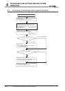
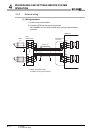
This section describes the wiring precautions and module connection example.
4.4.1 Wiring precautions
External wiring that is less susceptible to noise is required as a condition of configuring a
highly-reliable system and making full use of the capabilities of Q68RD3-G.
Precautions for external wiring are described below.
(1) Use separate cables for the AC control circuit and the external input
signals of the Q68RD3-G to avoid the influence of the AC side surges
and inductions.
(2) Always place a RTD at least 100mm (3.94 inch) away from the main
circuit cables and AC control circuit lines. Fully keep it away from high-
voltage cables and circuits, which include high frequency waves, such
as an inverter's load circuit. Not doing so will cause the module more
susceptible to noises, surges, and inductions.
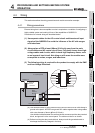
(3) The following wiring is required for the product to comply with the EMC
and Low Voltage Directives.
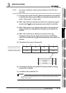
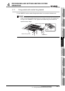
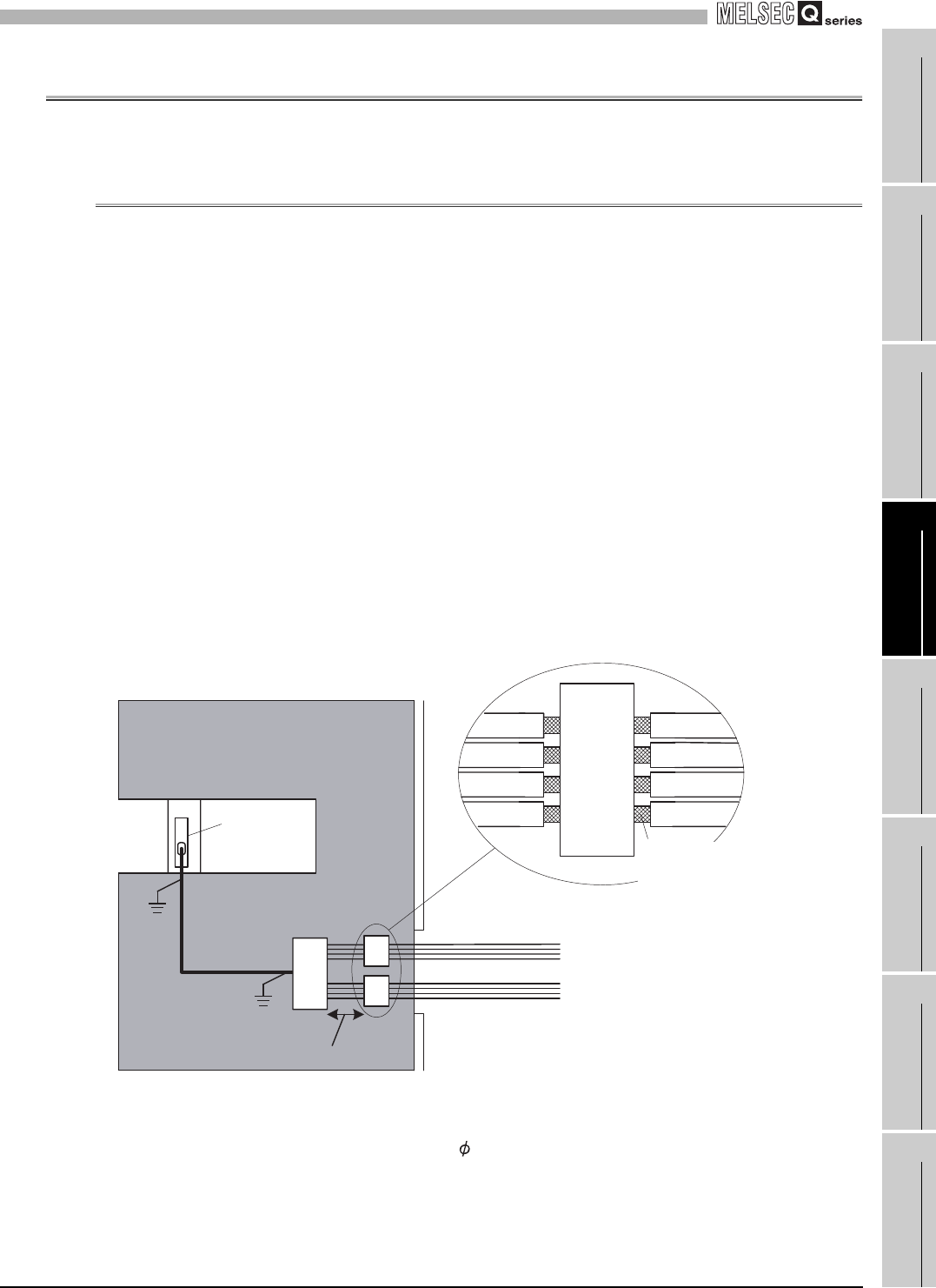
(a) Use shielded cables for every external wiring and use the AD75CK cable clamp to
ground to the panel. AD75CK can ground four cables together when using cables
with outer diameter of about 7mm (0.28 inch).
Use shielded cabled between the external device connector and the relay terminal
block, and ground it to the control panel. The cable must be 3m or shorter.
(b) Before touching the relay terminal block, always touch the grounded metal to
discharge the electricity charged in the body.
External
device
connector
20 to 30cm (7.87 to 11.81 inch)
Strip off the
outer sheath
Relay
terminal
block
In a control panel
Q68RD3-G
AD75CK