


5 - 35
CHAPTER5 MEMORIES AND FILES USED FOR CPU MODULE
1
2
3
4
5
6
7
8
5.3 File Operations by GX Developer and Handling Precautions
5.3.3 File size
*1: The value is adjusted by the system so that the total bytes with the addition of the network parameter setting may be multiple of four.
*2: The value is adjusted by the system so that the bytes may be multiple of four.
*3: 148 is set by default (This value depends on the parameter setting).
*4: After the decimal point of a value found by the number of bit device points/16 is rounded up.
*5: For the Universal model QCPU, if the serial number (first five digits) is "10011" or earlier, apply the number of execution programs.
*6: The Q00UJCPU does not support this function.
*7: When using the index register as a local device for the Q03UDCPU, Q04UDHCPU, Q06UDHCPU, Q13UDHCPU, Q26UDHCPU, or
Built-in Ethernet port QCPU, check the versions of the CPU module and GX Developer.
( Appendix 2)
*8: When using the module error collection, check the versions of the CPU module and GX Works2.
( Appendix 2)
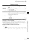
Remark
For calculation example of memory capacity, refer to Section 5.3.4.
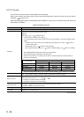
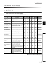
Table5.8 Calculation of file size(continued)
Function Rough file capacity (unit: Byte)
Sampling trace file
*6
362 + (number of word device points + number of bit device points) 12 + (N1 + N2 + N3 + number of
word device points 2 + (number of bit device points/16) 2) the number of traces (total number of
executions)
*4
• Apply the following values to N1 to N3 according to the items set in "Trace additional information" of the
Trace condition settings screen. ( Section 6.14(4)(b))
N1: When "Time" is set, apply "4".
N2: When "Step no." is set, apply "10".
N3: When "Program name" is set, apply "8".
Device data backup file Setting value at formatting (2 to 1024K)
Module error collection file
*8
76 + (64 (value set for the number of storable errors))
Local device
*6
72 + 6 (set device type) + 2 ((total number of M and V points)/16 + (number of D points) + 18 (total
number of T, ST, and C points)/16)) (number of programs where local devices are used
*5
)
• M, V, D, T, ST, and C indicate the following set devices.
M: internal relay
V: edge relay
D: data register
T: timer
ST: retentive timer
C: counter
Z: index register*
7