6 - 116
6.21 LED Indication
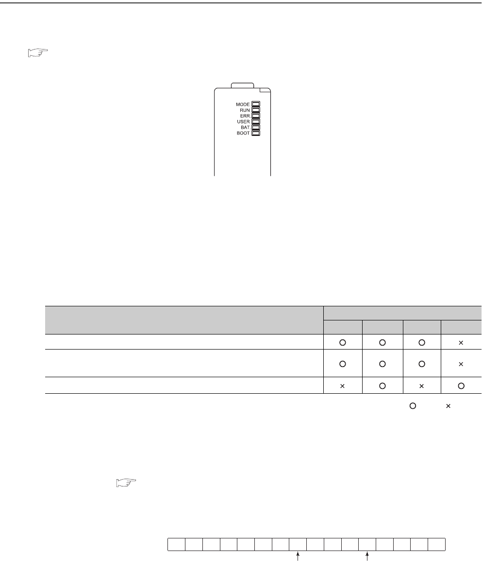
Operating status of the CPU module can be checked by the LEDs on the front of the CPU module.
For details of LED indications, refer to the following.
QCPU Userís Manual (Hardware Design, Maintenance and Inspection)
6.21.1 Methods for turning off the LEDs
(1) Methods
The LEDs can be turned off by the following operations (except for reset operation).
: Valid, : Invalid
*1: Description of special relays and special registers
Configure setting to turn off each LED as follows:
•
Turning off both the Boot LED and USER LED: SD202 = 110
H
•
Turning off only the BOOT LED: SD202 = 100
H
•
Turning off only the USER LED: SD202 = 10
H
Figure 6.87 LEDs on the front of the CPU module
Table6.35 Methods for turing off the LEDs
Method for turning off the LED
Relevant LED
ERR. USER BAT. BOOT
Execute the LEDR instruction after resolving the error.
After resolving the error, clear the error by the special relay SM50 and special
register SD50
*1
(operation continuation error only).
Turn off the LED by the special relay SM202 and special register SD202.
*1
• SM50 : Clears an error of the error code stored in SD50 when the CPU module is powered off and then on.
•SD50
:
Stores an code of an error to be ccleared.
For details of error codes, refer to the following.
QCPU Userís Manual (Hardware Design, Maintenance and Inspection)
• SM202 : Turns off the LED corresponding to each bit of SD202 when the CPU module is powered off and then on.
• SD202 : Set an LED to be turned off.
Figure 6.88 Bit structure of the special register SD202
b15 b8 b4 b0
SD20
1/0 1/0
BOOT LED USER LED
0: Not turn on.
1: Turns on.


