


CHAPTER9 DEVICES
9
2
3
4
5
6
7
8
9.2 Internal User Device
9.2.12 Data register (D)
9 - 31
9.2.12 Data register (D)
(1) Definition
The data register (D) is a memory in which numeric data (-32768 to 32767, or 0000H to FFFFH) can be
stored.
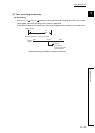
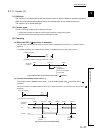
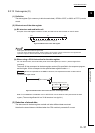
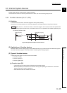
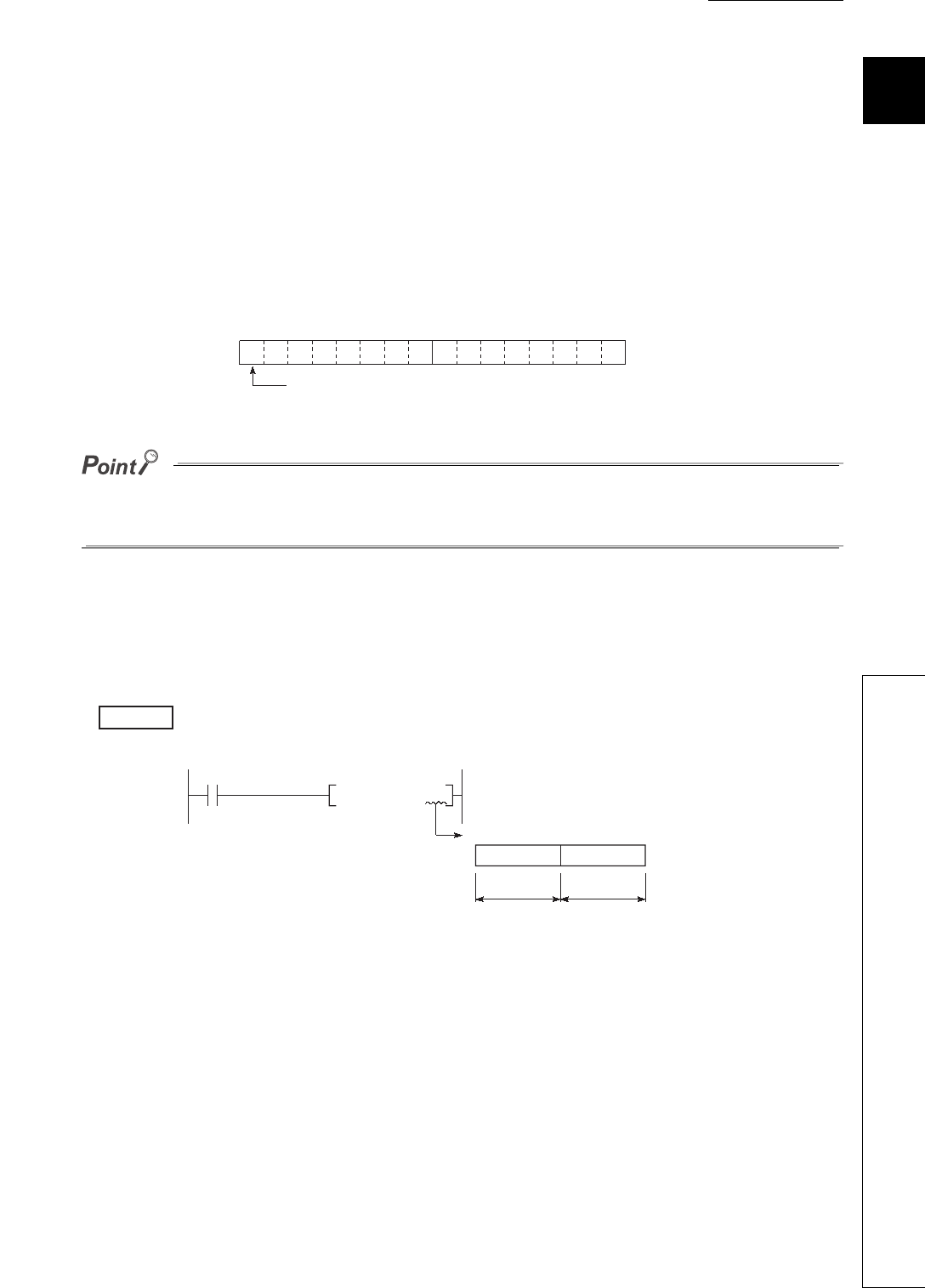
(2) Bit structure of the data register
(a) Bit structure and read/write unit
One point of the data register consists of 16 bits, and data can be read or written in units of 16 bits.
Data register data are handled as signed data.
In the case of the hexadecimal notation, 0000
H to FFFFH can be stored. However, because the most significant bit
represents a sign bit, decimal values that can be specified are -32768 to 32767.
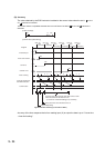
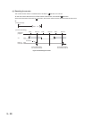
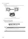
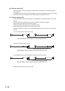
(b) When using a 32-bit instruction for the data register
For a 32-bit instruction, two consecutive points of the data register (Dn and Dn+1) are the target of the
processing.
The lower 16 bits correspond to the data register number (Dn) specified in the sequence program,
and the higher 16 bits correspond to the specified data register number + 1.
When D12 is specified in the DMOV instruction, D12 represents the lower 16 bits and D13
represents the higher 16 bits.
Data of -2147483648 to 2147483647 or 0
H to FFFFFFFFH can be stored in a two-point area of the data
register. (The most significant bit in a 32-bit structure is a sign bit.)
(3) Retention of stored data
The data stored in the data register are held until other different data are stored.
Note that the stored data are initialized when the CPU module is powered off or reset.
Figure 9.38 Bit structure of the data register
Figure 9.39 Data transfer with a 32-bit instruction and storage location
Dn
b15
to
b0
Most significant bit represents a sign bit.
Example
K500000
D12
DMOV
D13
D12
Processing target: D12, D13
Upper 16 bits Lower 16 bits