


6 - 78
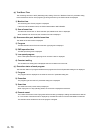
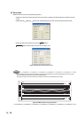
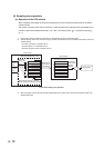
(4) Sampling trace operation
(a) Operation of the CPU module
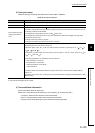
When a sampling trace trigger is issued by GX Developer, the CPU module executes traces for the preset
number of times.
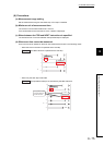
The number of traces will be a value of which the number of bytes for the sampling trace area divided by the
number of bytes of the specified device (N1 + N2 + N3 + word device points 2 + (bit device points/16)
2).
*1 *2
*1: Round up the result of "bit device points/16" in the expression to the right of the decimal point.
*2: Add the following values to N1 to N3 according to the items selected under the trace additional information of the trace
condition setting.
•N1: When "Time(sec)" is selected, add "4".
•N2: When "Step no." is selected, add "10".
•N3: When "Program name" is selected, add "8".
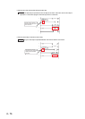
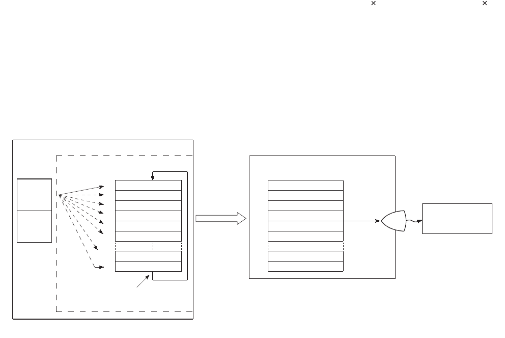
*3: When the trigger is issued, the CPU module samples data for the preset number of times and latches the data in the
sampling trace area.
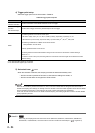
Figure 6.64 Sampling trace operation
CPU module
Standard RAM/memory card
*3
Specified
device data
Sampling trace area
Device
area
File
register
area
1st trace data
2nd trace data
3rd trace data
4th trace data
5th trace data
6th trace data
(n-1)th trace data
n th trace data
n-1
1
2
3
4
5
6
1
2
3
4
5
6
nn
n
-1
When data is stored for n th time,
the next data overwrites the 1st data.
Read out the
trace data to
a peripheral.
Sampling trace area
The specified
number of trace
data sets is
displayed.
Sampling trace
GX Developer