


CHAPTER6 FUNCTIONS
1
2
3
4
5
6
7
8
6.14 Sampling Trace Function
6 - 83
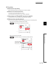
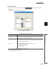
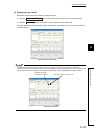
2) Trace point setup
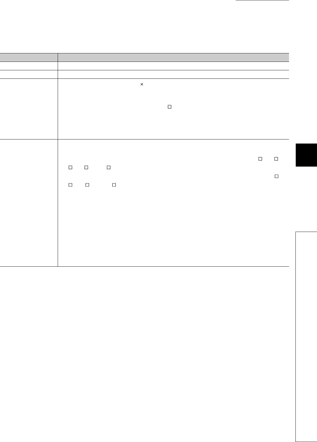
Select the timing for collecting trace data from the items listed in Table6.23.
*1: The extended data register (D) is included.
*2: The extended link register (W) is included.
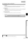
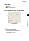
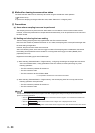
3) Trace additional information
Set the information added for each trace.
Select one or more items from the following. (If not necessary, do not select any item.)
• Time(sec.): Stores the time when the trace was executed.
• Step no.: Stores the step number where the trace was executed.
• Program name: Stores the program name where the trace was executed.
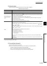
Table6.23 Trace point setup item
Item Description
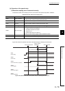
Each scan Collects trace data during END processing of each scan.
Interval Collects trace data at specified time intervals.
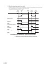
Each multiple CPU high
speed communication
cycle
*1
Collects trace data in a cycle of 0.88m specified time intervals.
Since data is collected at the timing of interrupt program (I45) execution, trace data can be collected only when
the following conditions are all satisfied.
• The multiple CPU high-speed main base unit (Q3 DB) is used.
• The multiple CPU system where two or more CPU modules are used and the multiple CPU high speed
transmission function is set.
• Interrupt pointer (I45) exists in a program.
• Interrupts are enabled and interrupt mask of I45 is cancelled.
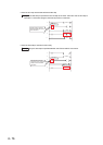
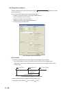
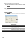
Detail
A trace point (device and/or step number) needs to be set.
The following devices can be set as a trace point.
• Bit device: X(DX), Y(DY), M, L, F, SM, V, B, SB, T(contact), ST(contact), C(contact), FX, FY, J \X, J \Y,
J\B, J\SB, BL\S
• Word device: T(current value), ST(current value), C(current value), D
*1
, SD, W
*2
, SW, R, Z, ZR, FD, U \G,
J\W, J\SW, U3E\G
The following modifications are available for the above devices.
• Digit specification of bit device
• Bit specification of word device
• Indirect specification of word device
• Index modification
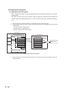
The setting method and trace data collection timing are same as those for the monitor condition setting in
Section 6.11.1.
If a device is set as a trace point, the timing when the word device value is changed can be selected as a data
collection timing.