


App - 38
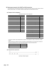
(c) Program after replacement
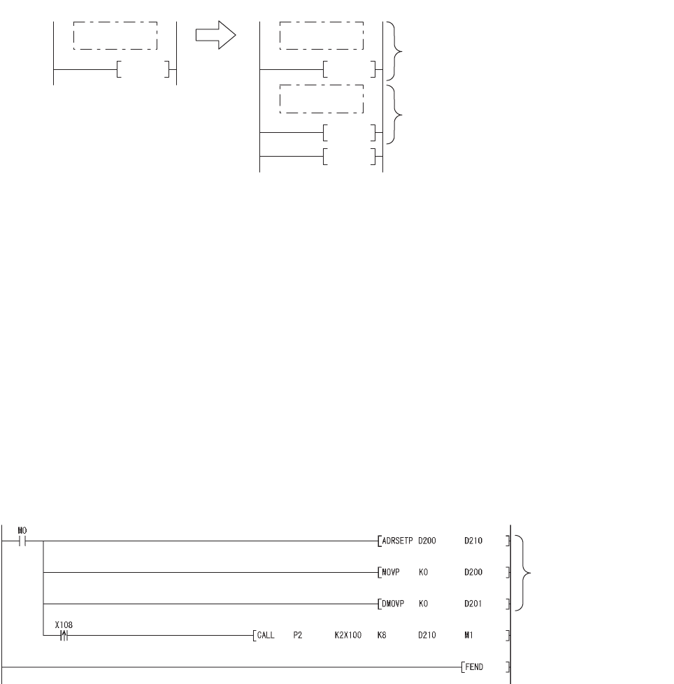
In the sequence program after replacement, two programs are required as shown below.
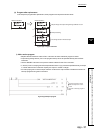
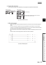
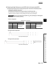
1) Main routing program
• Set "0" in the input data area on the rising edge of the execution instruction ("M0" in the program below)
and initialize the program.
• Execute the CALL instruction on every rising edge of the strobe signal ("X108" in the program below) so
that a subroutine program is called.
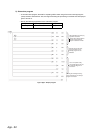
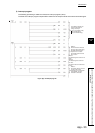
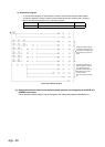
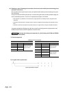
• In the subroutine program, input codes are added to the input data area and the completion status is
checked.
• Pass the following data to the subroutine program at execution of the CALL instruction.
1) ASCII code input values from the input module (Xn0 to Xn7)
2) Number of digits to be input
3) Indirect address of the input data area (Use the ADRSET instruction to acquire the indirect
address for the input data area.)
4) Bit devices to be turned on when input is completed
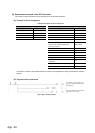
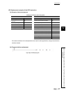
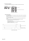
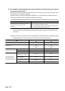
Figure App.16 Program execution
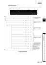
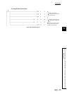
Figure App.17 Sample program
FEND
RET
END
<After transition>
END
<Before transition>
Initial processing
ASCII code is added to the input data area.
P2
Main routine
program
Main routine
program
Subroutine
program
The input data area is initialized.
A subroutine program is called at
the rising edge of the strobe signal.