


6 - 8
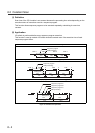
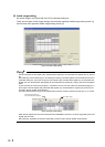
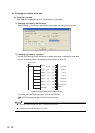
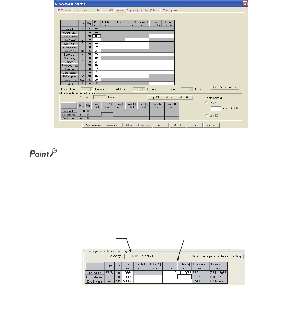
(5) Latch range setting
Set a latch range in the Device tab of the PLC parameter dialog box.
There are two types of latch range settings: the latch clear operation enable range setting (Latch (1))
and the latch clear operation disable range setting (Latch (2)).
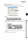
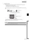
The latch range of the file register (ZR), extended data register (D), and extended link register (W) can also be
set.
After selecting "Use the following file." and setting the capacity of the file register in the PLC file tab of the PLC
parameter dialog box, set a latch range of the file register (ZR), extended data register (D), and extended link
register (W). (For the extended data register (D) and extended link register (W), assign a part of the file register
area.)
If "Use the same file name as the program." is selected in the PLC file tab of the PLC parameter dialog box, a
latch range of the file register (ZR), extended data register (D), and extended link register (W) cannot be set.
(All data in the file register will be latched.)
The data outside the latch range will be cleared when the CPU module is powered off and then on or is reset.
When the file register file to be used is switched with the QDRSET instruction, the latch range setting of the file
register will be invalid.
After switching, regardless of the latch range setting, whole range of the file register will be latched.
Figure 6.4 Latch range setting
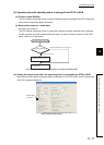
Figure 6.5 Latch range setting
The file register points set
in the PLC file tab is displayed.
Set a latch range.