


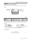
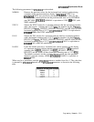
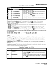
Trace Data Transfers with TDF P
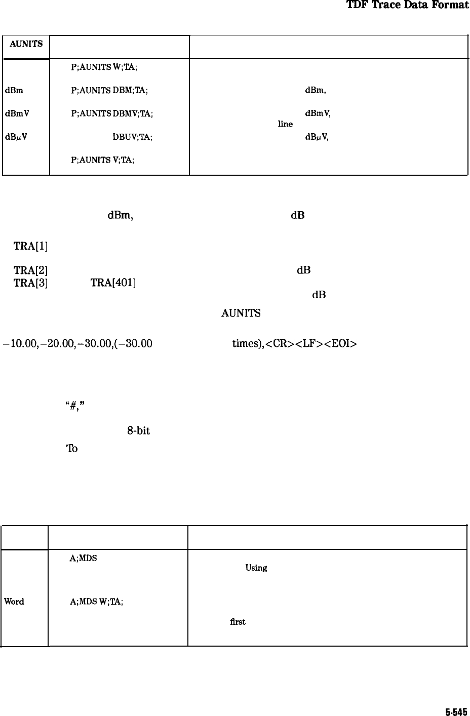
AUNITS
Setting
Watts
dBmV
dBpV
Volts
Example
Description
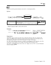
TDF
P;AIJNITS
W;‘L4;
TDF P;AUNITS
DBM;TA;
TDF P;AUNITS
DBMV;TA;
TDF P;AUNITS
DBUV;TA;
TDF P;AUNITS v;TA;
Transfers 401 real values, in watts, with each value separated by a
carriage return and a line feed.
Transfers 401 real values, in
dBm,
with each value separated by a
carriage return and a line feed.
Transfers 401 real values, in
dBmV,
with each value separated by a
carriage return and a line feed.
Transfers 401 real values, in dBpV, with each value separated by a
carriage return and a line feed.
Transfers 401 real values, in volts, with each value separated by a
carriage return and a line feed.
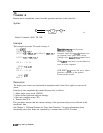
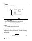
Example of how data is returned: For example, if the reference level of the spectrum
analyzer is set to -10
dBm,
the amplitude scale is set to 10
dB
per division, and trace A
contains the following data:
TRA[l]
contains 8000 (in measurement units). The value 8000 indicates trace element 1 is at
the reference level.
TRA[B]
= 7000 measurement units (trace element 2 is -10
dB
below the reference level).
TRA[3]
through
TRA[401]
each contain 6000 (in measurement units). The value 6000
indicates that the trace elements 3 through 401 are all at -20
dB
below the reference level.
Querying trace A with the TDF P format and
AUNITS
set to DBM returns ASCII character codes
for the following:
-lO.OO,-20.00,-30.00,(-30.00 is repeated 398 times),<CR><LF><EOI>
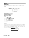
TDF A
Description: TDF A is the A-block data format. With the A-block data format, trace data is
preceded by
“#,
”
“A,” and a two-byte number (the two byte number indicates the number
of trace data bytes). The setting of the MDS command determines whether the trace data is
transferred as one or two
g-bit
bytes.
Restrictions:
To
use the A-block format for sending data, you must provide the number of
data bytes.
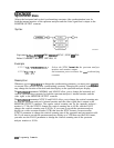
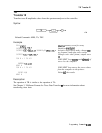
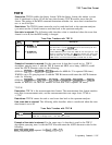
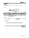
How data is returned: The following table describes what is transferred when the trace data
format is set to A, but the MDS setting is changed.
MDS
setting
Binary
Trace Data Transfers with TDF A
Example
Description
TDF
A;MDS
B;TA;
TDF
A;MDS
W;TA;
Transfers “#A,” the number of bytes of trace data, then the 401 bytes
of trace data.
Using
MDS B “reduces” each trace value into one byte
by dividing (DIV) the trace value by 32. The trace data transfer is
ended with an EOI.
Transfers “#A,” the number of bytes of trace data, then 802 bytes of
trace data. MDS W uses two bytes per trace element to transfer trace
data. The
ilrst
byte contains the trace value divided by (DIV) 256, the
second byte contains the remainder (MOD) of that division. The trace
data transfer is ended with an EOI.
Programming Commands
5-545