


C
RS-232 and Parallel Option 043
What You’ll Learn in This Appendix
This appendix explains how to connect a computer to your HP 8590 Series Option 043 spectrum
analyzer using the RS-232 interface. It contains information pertaining to RS-232 signals, cable
connections, and baud rate.
Introducing the RS-232 Interface
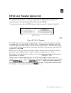
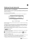
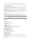
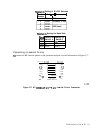
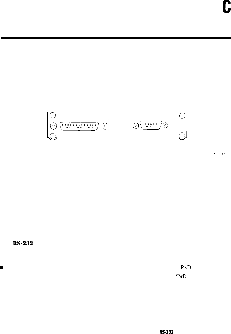
Your spectrum analyzer has an RS-232 connector on the rear panel, as shown in Figure C-l.
lo
PARALLEL
0
SERIAL
10.
.oJ
v
OPTION 043
V
cu134e
Figure C-l. RS-232 Connector
The RS-232 interface utilizes serial data transmission. Data is sent, one bit at a time, in groups
of 10 to 12 data-bits.
Two devices, such as the spectrum analyzer and a computer, can exchange commands and data
over the RS-232 connection. This interface uses two serial data lines and five handshaking
lines. Handshaking signals are required for full hardware control of the information exchange.
It is possible to use a three-wire connection, in some situations.
Another parameter for the RS-232 interface is the “baud,”
or data rate. This is the speed at
which the computer and spectrum analyzer exchange data. The baud rate of each of the two
RS-232 devices must be the same.
The
W-232
Data Lines
RS-232 uses serial data transmission, meaning that data is transmitted one bit at a time. There
are two data lines carrying signals:
w
Transmit data (TxD)-the serial data output. This line is connected to the
RxD
input line.
n Receive data (RxD)-the serial data input. This line is connected to the
TxD
output line.
The RS-232 Handshaking Lines
In addition to the data signals, there are five other signals lines (called handshaking lines), used
to control the flow of data. Listed below are the handshake signal descriptions:
n Request to send (RTS)-Output signal indicates that the spectrum analyzer is ready to
communicate. This line is true at power-up and stays true while power is on.
M-232
and Parallel Option 043
C-l