


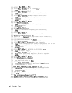
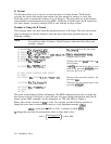
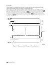
A-Block Format
The A-block format is similar to binary format in that each data point is sent as two 8-bit bytes
(this, too, is in the internal representation of measurement data). A-block format also transfers
a four-byte header before the 401 points of trace data. These bytes are the ASCII character
“f’,
“A”, and two-byte number representing the length of the trace data, followed by the data
bytes.
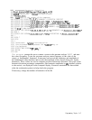
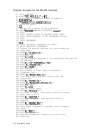
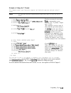
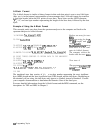
Example of Using the A-Block Format
This example sends trace data from the spectrum analyzer to the computer and back to the
spectrum analyzer in A-block format.
10 INTEGER
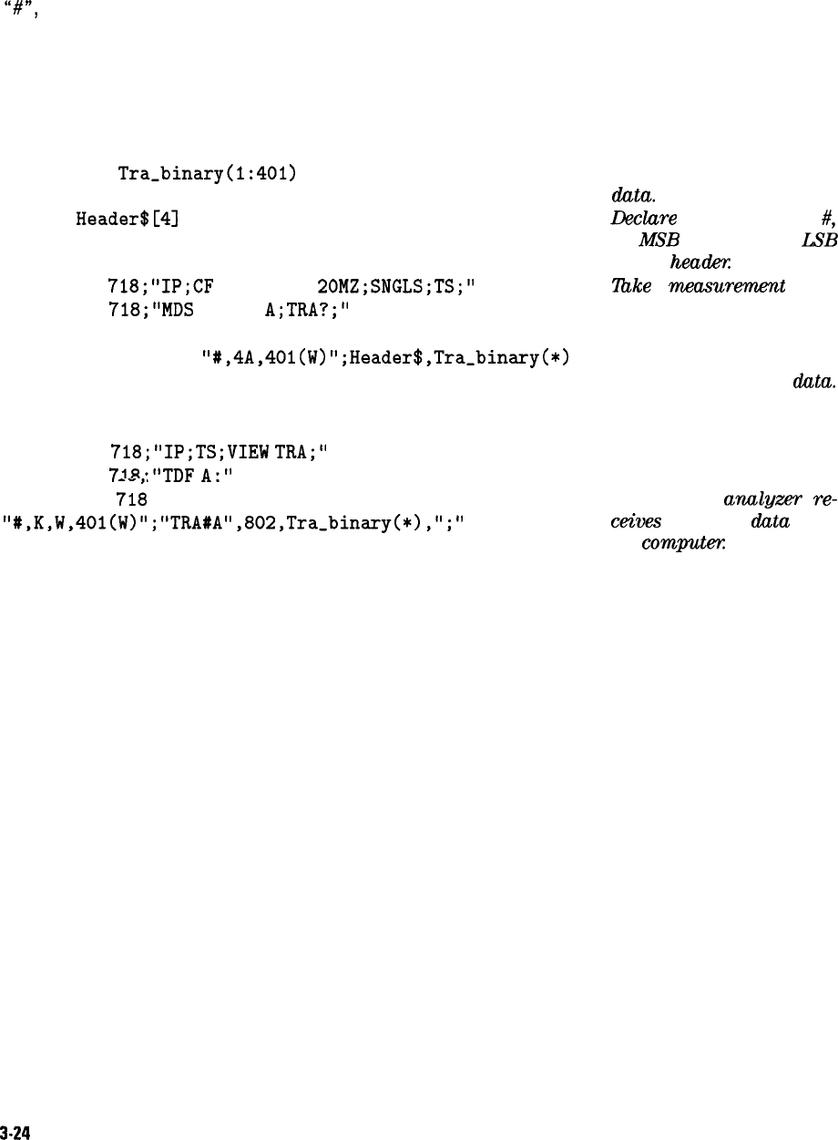
Tra_binary(l:401)
20 DIM
Header$[4]
Declare an array for trace
data.
Declare
a string for the
#,
A,
MSB
length, and LSB
length
heao!.ex
30 OUTPUT
718;"IP;CF
300MZ;SP
20MZ;SNGLS;TS;"
40 OUTPUT
718;"MDS
W;TDF
A;TRA?;"
llxke
a
mxxzsurem.ent
sweep.
Send trace A to the com-
puter in A-block format.
50 ENTER 718 USING
"#,4A,401(W)";Header$,Tra_binary(*)
The computer receives the
header and the trace
data.
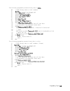
60 PRINT "PRESS CONTINUE TO RETURN DATA TO THE ANALYZER"
70 PAUSE
80 OUTPUT
718;"IP;TS;VIEW
TRA;"
View trace A.
90 OUTPUT
718e"TDF
A-"
100 OUTPUT
71;
USING'
The spectrum
anulgzer
re-
"#,K,W,40l(W)"; "TRA#A",802,Tra_binary(*),";"
wives
the trace
data
from
the computex
110 END
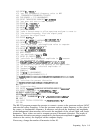
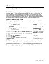
The transferred trace data consists of
#A,
a two-byte number representing the most significant
byte (MSB) length and the least significant byte (LSB) length, and the data bytes. Depending on
the terminal you are using, the data bytes may appear as symbols instead of numbers. Consult
your computer documentation to determine the numeric value of the data bytes.
For more detailed information about the A-block format and the MDS command, see the
descriptions for TDF and MDS in Chapter 5.
3-24
Programming Topics