


Emerson Process Management GmbH & Co. OHG 4-13
X-STREAM XE
Instruction Manual
HASXEE-IM-HS
04/2010
4
Installation
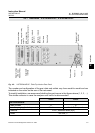
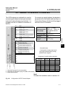
Pin Signal
P2.1 Channel 1, (+) 4 (0) - 20 mA
P2.2 Channel 1, GND
P2.3 Channel 2, (+) 4 (0) - 20 mA
P2.4 Channel 2, GND
P2.5 Channel 3, (+) 4 (0) - 20 mA
P2.6 Channel 3, GND
P2.7 Channel 4, (+) 4 (0) - 20 mA
P2.8 Channel 4, GND
P2.9 Channel 5, (+) 4 (0) - 20 mA (in preparation)
P2.10 Channel 5, GND (in preparation)
P2.11 not used
P2.12 not used
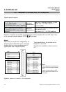
P3.1 not used
P3.2 not used
P3.3 Output 1 (Failure), NC
P3.4 Output 1 (Failure), NO
P3.5 Output 1 (Failure), COM
P3.6 Output 2 (Maintenance Request), NC
P3.7 Output 2 (Maintenance Request), NO
P3.8 Output 2 (Maintenance Request), COM
P3.9 Output 3 (Out of Spec), NC
P3.10 Output 3 (Out of Spec), NO
P3.11 Output 3 (Out of Spec), COM
P3.12 Output 4 (Function check), NC
P4.1 Output 4 (Function check), NO
P4.2 Output 4 (Function check), COM
P4.3 not used
P4.4
P4.5
P4.6
P4.7
P4.8
P4.9
P4.10
P4.11
P4.12
Relay Outputs
**)
Analog Outputs
Serial Interface
*)
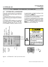
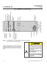
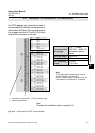
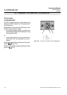
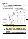
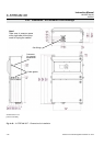
4.5.1 Installation - X-STREAM XEGC, X-STREAM XEGP
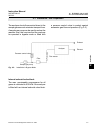
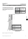
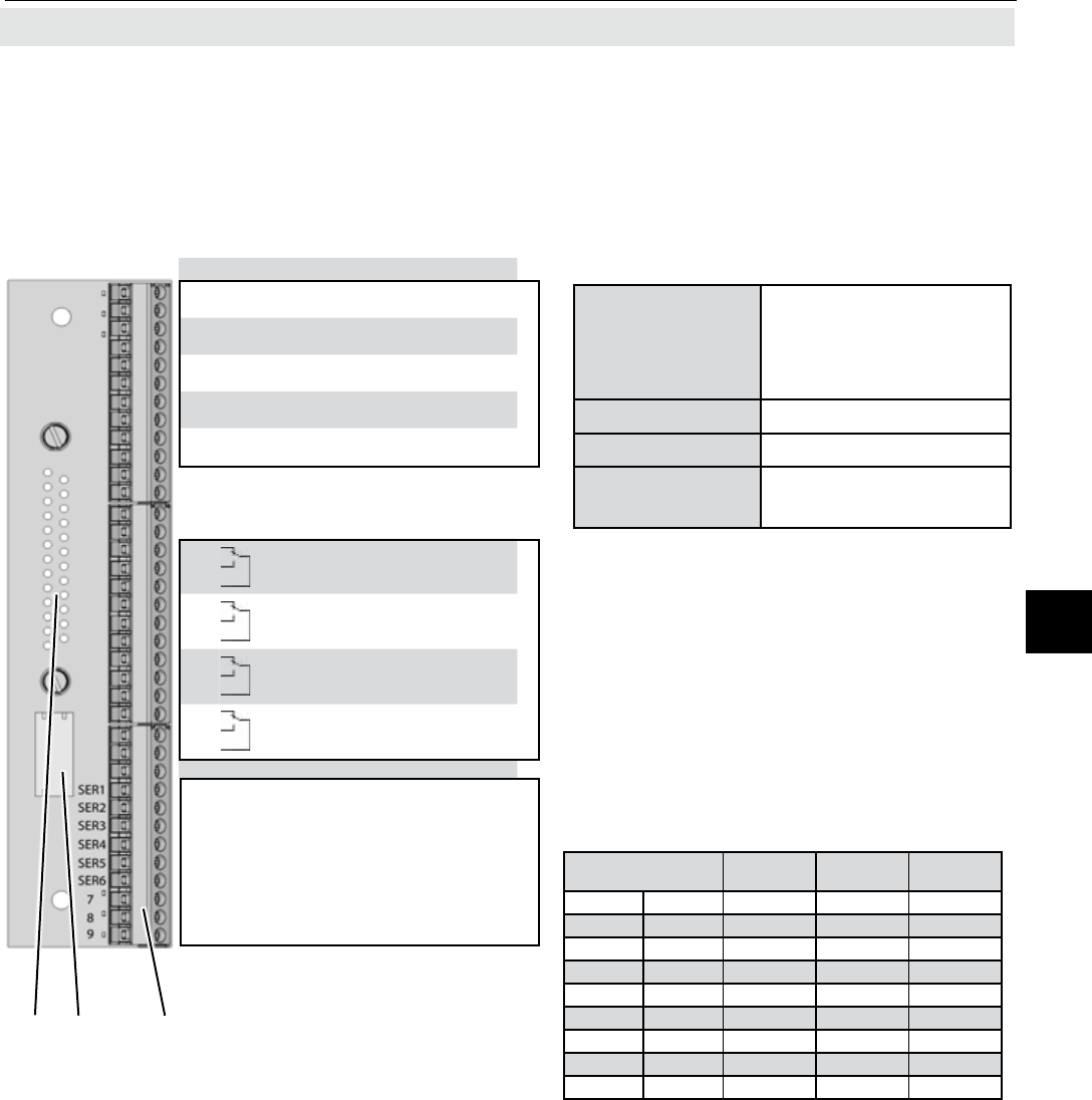
Fig. 4-9: Conguration of XSTA Terminal Adapter
To connect any serial interface, the adapter is
equipped with a at exible cable ending in a
9-pin submin-D plug, which should be plugged
onto the unit’s X2 connector.
1 Connector for plug X1 (on reverse side)
2 Connection for at cable to plug X2 (cable not illustrated)
3 Screw-type terminals
Note!
Consider the installation notes in section 4.6.
The XSTA adapter can optionally be used to
connect signal cables to screw-type terminals
instead of submin-D plugs and sockets: it is
plugged onto the X1 Submin-D connector on
the unit.
1 2 3
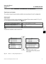
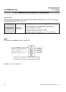
Assignment of serial interface terminals
*)
See table below
**)
Conguration of relay output termi-
nals as per standard factory setting
(NAMUR status signals)
Recommended
wire gauge:
0.14 ... 1.5 mm
2
(AWG 26 ... AWG 16)
end sleeves not re-
quired
Skinning length: 5 mm (0.2")
Thread: M2
Min. tightening
torque:
0.25 Nm
(2.21 in.lb)
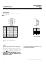
Terminal
MOD 485/
2 wire
MOD 485/
4 wire
RS 232
P4.4 SER1 Common Common Common
P4.5 SER2 not used not used RXD
P4.6 SER3 not used not used TXD
P4.7 SER4 not used RXD1(+) not used
P4.8 SER5 D1(+) TXD1(+) Common
P4.9 SER6 not used not used not used
P4.10 7 not used not used not used
P4.11 8 not used RXD0(-) not used
P4.12 9 D0(-) TXD0(-) not used