


Emerson Process Management GmbH & Co. OHG7-12
X-STREAM XE
Instruction Manual
HASXEE-IM-HS
10/2010
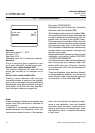
7.4.1 Preparing a Calibration
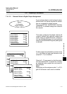
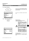
7.4.1.1.1 Internal Valve Assignment
If your analyzer provides internal valves, at
rst
open SETUP - IN-/OUTPUTS - INTERNAL
SHS
to assign the valves to the gas inlets:
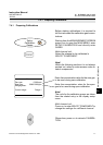
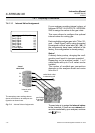
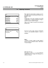
This menu allows to congure the optional
internal valves for routing gas.
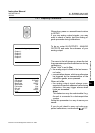
Each available analyzer gas inlet ("Gas1 Si-
gnal ... Gas8 Signal") with a valve connected
is assigned a virtual valve label (V1...V8). (If
the components have been installed in the
factory, the conguration is already setup).
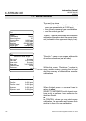
Notes!
If already factory setup, changing the con-
guration could result in inproper operation!
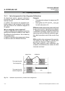
Depending on the analyzer model, 1 or 2
valve blocks with up to 4 or 8 valves can be
installed.
The number of available gas connections
depends on the analyzer model and varies
from 4 to 8.
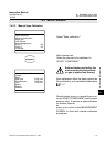
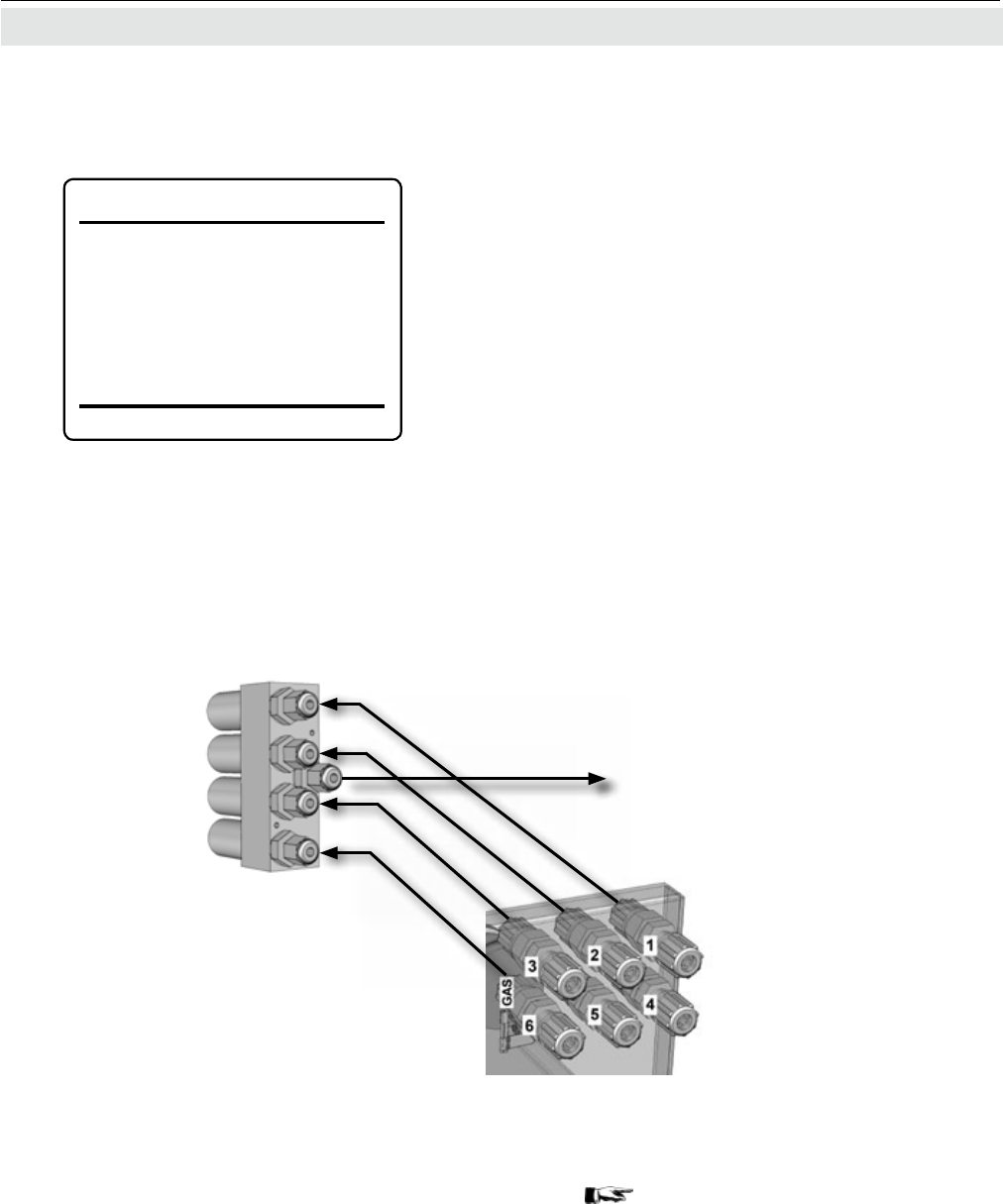
The exemplary menu settings shown
above could relate to an analyzer con-
guration as shown here.
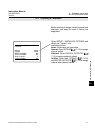
The next step is to assign the internal valves
to the channels. If there are no external val-
ves to be controlled by your analyzer, continue
with 7-15.
Fig. 7-3: Internal Valves Assignments
valve block outlet
to measuring cell
internal valve
block
virtual
valve label
V4
V1
V3
V2
gas ttings
at analyzer
rear side
tubings
Internal SHS (1of2)
Gas1 Signal: V4
Gas2 Signal: V1
Gas3 Signal: V3
Gas4 Signal: Off
Gas5 Signal: Off
Gas6 Signal: V2
Gas7 Signal: Off
Gas8 Signal:
Off