Emerson Process Management GmbH & Co. OHG 8-39
X-STREAM XE
Instruction Manual
HASXEE-IM-HS
06/2010
8
Troubleshooting
8.4 Troubleshooting on Components
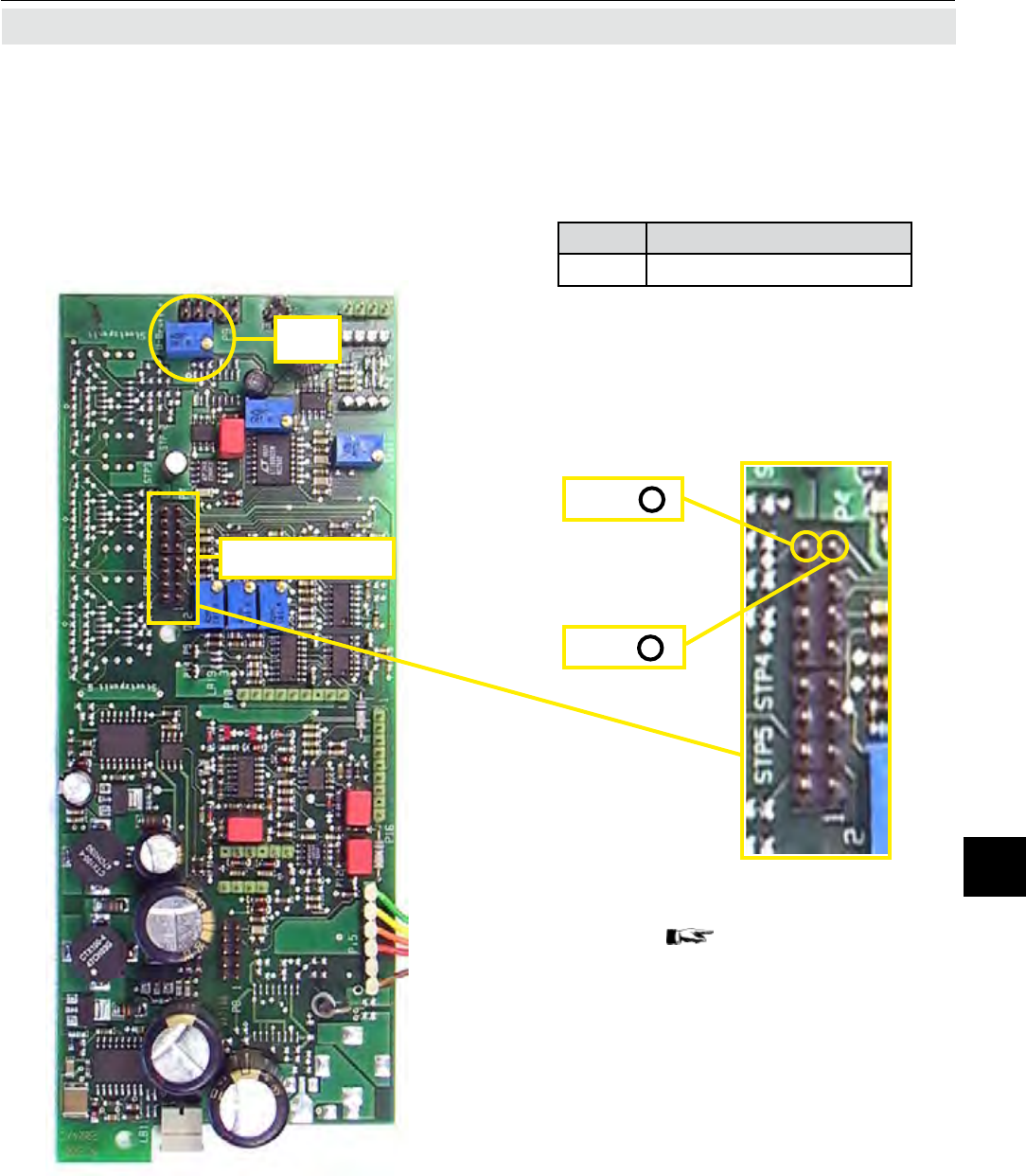
R60
Test connector P4
P4.15
P4.16 +
_
Step 3:
Locate test connector P4 to measure
the bridge voltage:
P4.16 Bridge voltage (+)
P4.15 Bridge voltage (-); GND
CAUTION!
Do not short-circuit pins!
Alternatively the GND signal (-) is ac-
cessible on the main board BKS, too:
Locate X11 (
g. 8-3, page 8-16) .
The bridge voltage depends on range
and sample gas and should be bet-
ween 3V and 5V.
Only if the WAP 100 board has been
replaced, it is necessary to adjust the
voltage with potentio-meter R60.


