


Emerson Process Management GmbH & Co. OHG 4-21
X-STREAM XE
Instruction Manual
HASXEE-IM-HS
04/2010
4
Installation
4.5.2 Installation - X-STREAM XE Field Housings
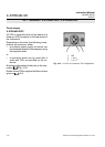
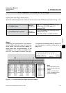
Power and signal cables are connected using
internal screw-type terminals. This requires
opening the unit, which in turn requires relea-
sing the fasteners on the housing.
Gas connectors are accessible from the out-
side, on the underside of the instrument.
The number and conguration of the gas
inlets and outlets depends on the analytical
application, and is noted on a sticker on the
underside of the instrument next to the con-
nectors.
To simplify installation, we recommend label-
ling the gas lines in accordance with these
markings. This avoids confusion should the
analyzer need to be disconnectedfor main-
tenance.
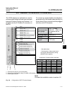
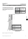
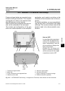
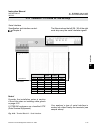
Fig. 4-17: X-STREAM XE Field Housing - Arrangement of Terminals, Cable Glands and Gas Connectors
5 Glands for signal cables
6 Gas inlets and outlets
7 Plugs for openings to connect housings
8 Ethernet connectors (optional)
1 Terminals for signal cables
2 Mains lter
3 Power connections with integrated fuses
4 Gland for power cable
6
5
7
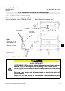
Gas inlets
Gas outlets
1
4
18 42 3
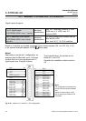
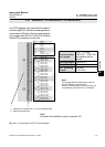
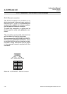
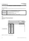
Note on XDF!
In case of the dual compartment
version XDF, the electrical con-
nections are established in the
upper compartment, and the
gas connections to ttings at the
lower compartment.
Besides this, the design and
layout of terminals and ttings
are the same as with the single
compartment version XEF.