


Emerson Process Management GmbH & Co. OHG4-28
X-STREAM XE
Instruction Manual
HASXEE-IM-HS
04/2010
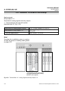
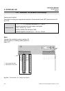
Analog Inputs
Pin Signal
P3.1 not used
P3.2 not used
P3.3 not used
P3.4 not used
P3.5 not used
P3.6 not used
P3.7 not used
P3.8 not used
P3.9 not used
P3.10 not used
P3.11 not used
P3.12 not used
P2.1 BR 1 t a wire bridge here to apply analog
P2.2 BR 1 signal in current mode to input 1
P2.3 Input 1 high (+)
P2.4 Input 1 high (+)
P2.5 Input 1 low (-)
P2.6 Input 1 low (-)
P2.7 BR 2 t a wire bridge here to apply analog
P2.8 BR 2 signal in current mode to input 2
P2.9 Input 2 high (+)
P2.10 Input 2 high (+)
P2.11 Input 2 low (-)
P2.12 Input 2 low (-)
{
}
{
}
IN1
Mode
IN2
Mode
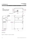
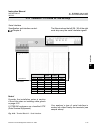
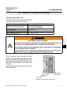
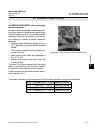
4.5.2 Installation - X-STREAM XE Field Housings
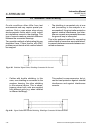
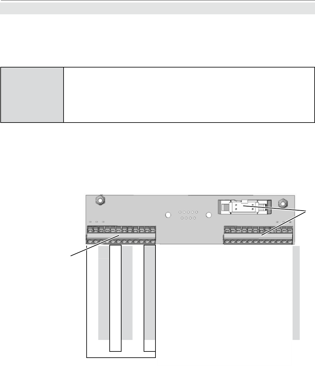
Fig. 4-22: Terminal Block X5 - Analog Input Signals
Note!
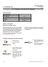
Consider the installation notes in section 4.6.
and the notes on installing cable glands on
page 4-22.
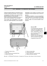
1 Screw-type terminals
2 Reserved for future use
1
2
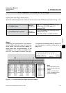
Analog inputs (option)
Terminals for analog input signals are located on the terminals board XSTI (terminal block X5;
g. 4-22).
2 analog inputs
0 - 1 V, 0 - 10 V (software selectable) R
in
= 100 kΩ
optional (requires to t wire bridges, see gure):
4 (0) - 20 mA ; R
in
= 50Ω
optically isolated from analyzer GND
protected against overload up to
±15 V or ±20 mA