


8
Connecting Telephones and Adjunct Systems
Installation and Wiring Telephones and Power Supplies
330 Installation and Upgrades for G700 and S8300
December 2003
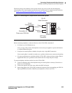
4 Install cross-connect jumpers to connect the pins from the 2-wire digital station to the appropriate
pins on the MM711 Media Module. Table 12, Two-Wire Station Pinout Chart,
on page 330 shows
a pinout chart for two-wire stations.
5 Administer using Administrator’s Guide for Avaya Communication Manager.
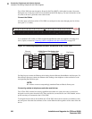
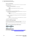
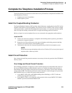
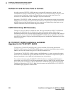
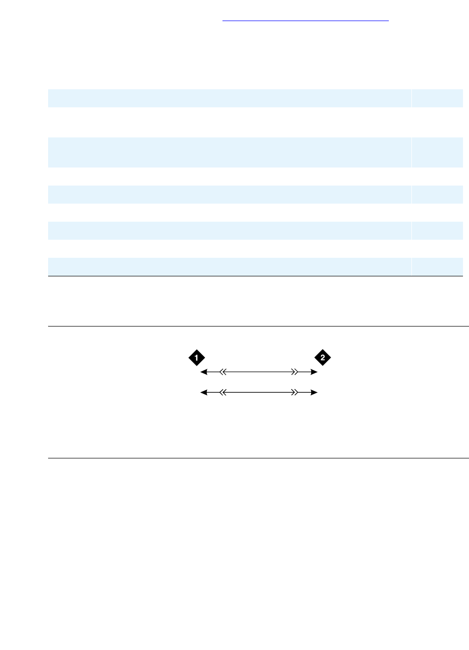
Figure 23: 2500-Type Analog Telephone Wiring
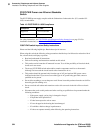
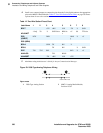
Table 12: Two-Wire Station Pinout Chart
Jack Name 1 2 3 4 5 6 7 8
BRI-T +TX +RX -RX -TX -V GND
ADJUNCT
+Vadj T0 -V GNDVoice RRVoic
e
+V S0 TTVoice
DSS
(QUEST)
DTX DRX OKdi
g
-V +V
DSS (ISDN)
BRI-A GND TX RX -V
BRI-U TX RX -V GND
DCP TX1 TX2 RX1 RX2 -V +V
ANALOG TIP RING
HANDSET -TX +RX -RX +TX
Figure notes
1 2500-Type Analog Station 2 MM711 Analog Media Module,
Position 1V301
2500wire RBP 071996
3
28
03
2T
R
T.3
R.3