


2
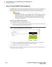
Installing Hardware for the G700 Media Gateway and S8300 Media Server
Installation and Cabling
84 Installation and Upgrades for G700 and S8300
December 2003
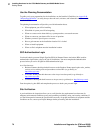
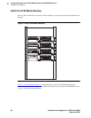
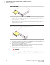
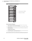
Figure 8: Insert S8300
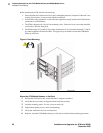
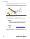
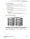
4 Align the LED module in its guides and gently push it into place, keeping the LED module safely
within its guides and maintaining an even pressure to assure that the module does not become
twisted or disengage from the guides.
Guide the longer, left side of the LED module into the chassis until the shorter, right edge of the
module can engage in its guides.
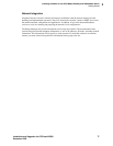
Figure 9: Align the LED module and the S8300 Media Server
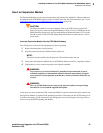
5 Push steadily and firmly until the faceplates of the S8300 Media Server and the LED module are
even and then push the two units into the housing together.
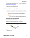
6 Apply firm pressure to engage the connectors.
The connector has different length pins. The long pins will engage first to provide grounding.
Medium length and short pins will provide power and signal.
7 Tighten the captive screws on the S8300 Media Server module.
!
WARNING:
To prevent access to electrical hazards by unauthorized personnel and to ensure
continued compliance to radiated emissions requirements, all captive screws must be
securely tightened such that they cannot be loosened without the use of a tool.