


Programming Function Blocks and Features
Video Recorder – User Manual 95
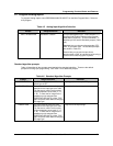
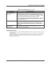
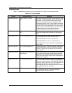
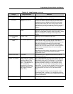
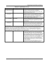
Table 4-10 Loop Prompts (continued)
Prompt Range/Selections Definition
ENGINEERING
UNITS
Select letter Units of measure for values of process variable or set point
which will appear on Online loop displays.
FEEDBACK OFF, analog parameter,
number
Provides verification to the loop that the loop output request
(LP OV) was achieved by the analog output module (AO).
Feedback sources are typically pointed to the associated
Back Calculation Value (BC) of an analog output module.
Feedback inputs must have a span equal to the loop output
span when they are not pointed directly to analog output
modules.
FEEDFORWARD OFF, analog parameter,
number
Modifies the control loop output independent of the PID
calculation. The range of the value should not exceed 0 to
100 units. Feedforward is typically used to provide an output
change in anticipation of a change to the loop process
variable.
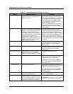
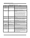
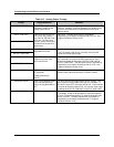
FEEDFORWARD
GAIN
-10.00 to 10.00 Applies gain to the feedforward input value.
FORCE REMOTE
MAN
OFF, discrete parameter, 0,
1
When discrete is ON(1), forces loop from automatic mode to
remote manual mode. In remote manual, loop output is
determined by the OUTPUT TRACKING value and the local
Down Arrow and Up Arrow buttons for manual output
adjustment are disabled. In remote manual the automatic
indicator (AUTO) of the display will flash. Selecting Manual
mode from the Auto/Manual button will override remote
manual operation.
When the loop’s Set point #2 is programmed as the Set point
Profiler (SPn OV), Force Remote manual should be
programmed as OFF.
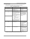
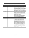
GAIN/PROP BAND PB or GAIN Select whether gain or proportional band will be used for
tuning the control loop.
GAIN#1 OR GAIN#2 Enter a value of 0.1 to 200
for Gain, or 0.5 to 1000.0 for
Proportional Band. Enter
OFF to allow integral only
control. (Variable Gain1 or
PB1 is available by
programming a constant's
Destination with GN or PB.
See Program Constants,
Section 4.16.)
Gain is the proportional gain entry for the control loop (The
value entered here is the gain applied to the error signal to
determine the loop output). For example, a 10% change in
process variable (with respect to the input range) from a
balanced condition will result in a 10% change in output,
when a gain of 1.0 is used. Enter a starting value at initial
configuration. The value may be altered Online for final loop
tuning. If an indirect source is specified as in an adaptive
gain configuration, the value can only be altered at the
source.
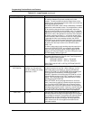
Gain and Proportional Band are interchangeable values
(Proportional Band = 100/Gain). For loops with dual tuning,
Gain 1 is the gain for the first set of tuning parameters. Gain
2 is for the second set.
HYSTERESIS Enter 0-100% of PV span Deadband value prevents excessive output oscillation when
using ON/OFF control.