


Programming and Operating Concepts
Video Recorder – User Manual 50
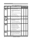
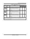
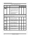
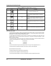
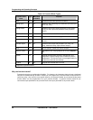
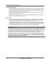
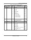
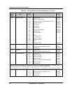
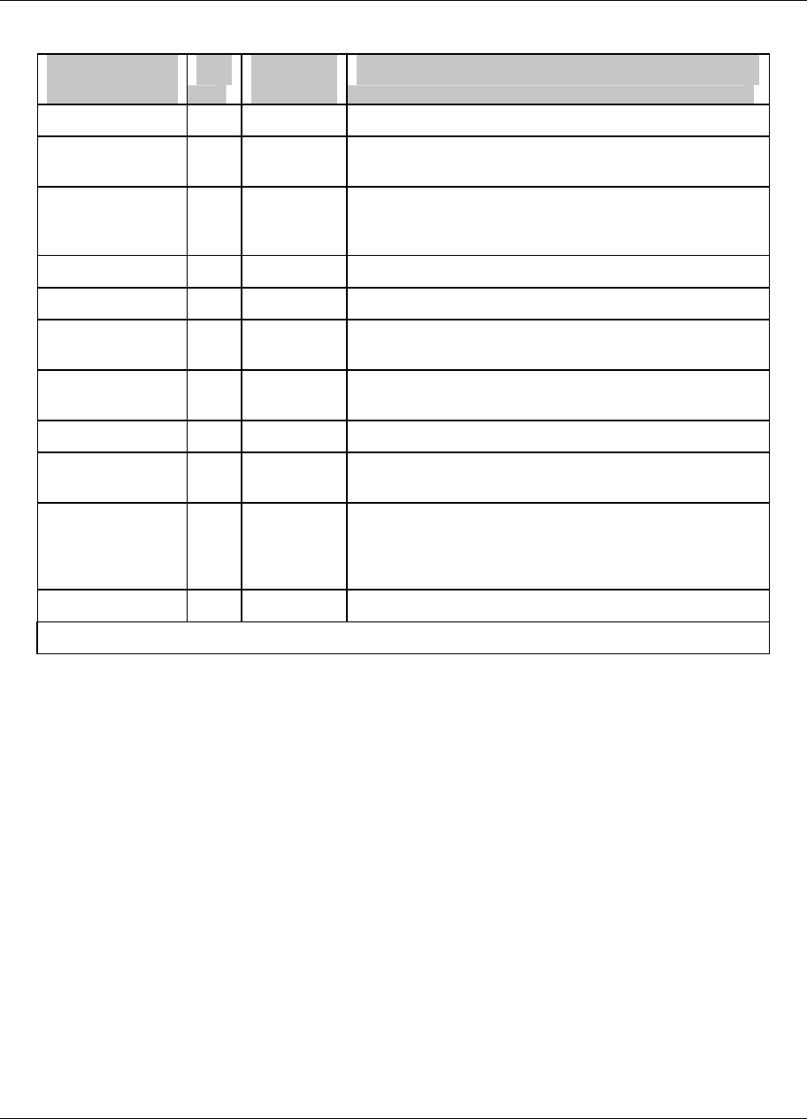
Table 3-3 Function Block Types
Function block
name
Type Maximum
available*
Purpose
Alarm AL 96 Causes alarms under specified conditions.
Analog Input AI 48 Interfaces with measuring input hardware (thermocouple,
RTD, mA, volts).
Analog Output AO 8 Interfaces with analog output hardware (current output
(CAT)) or with output relay hardware (time proportion
(DAT)).
Calculated Value CV 96 Performs various calculations on specified parameters.
Constant CN 32 Outputs a number or an analog parameter value.
Discrete Input DI 36 Interfaces with discrete input hardware (dry contact
closure).
Discrete Output DO 36 Interfaces with output relay hardware (AC relay, DC
relay, mechanical relay, open collector output).
Loop LP 8 PID or ON/OFF control with various outputs.
Setpoint Profiler SP 4
Generates a time-varying setpoint for a loop’s Setpoint
#2.
System SY 1 Outputs discrete status of alarms, data storage, and
diagnostics; outputs analog value of reference junction
temperature. This function block is not programmable; its
outputs are produced automatically.
Totalizer TL 48 Outputs accumulated total over time.
* Depends on options ordered.
Why use function blocks?
Function blocks give you configuration flexibility. For instance, the instrument does not have a dedicated
relay that is activated during an alarm; instead, you can program any of several Alarm function blocks to
control any relay. Also, there is not a specific input for your process variable; any of several Analog Input
function blocks can be programmed to be your process variable. In general, function blocks let you
connect the output parameter of any function block to the input parameter of any function block.