


Programming Function Blocks and Features
Video Recorder – User Manual 117
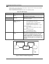
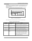
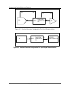
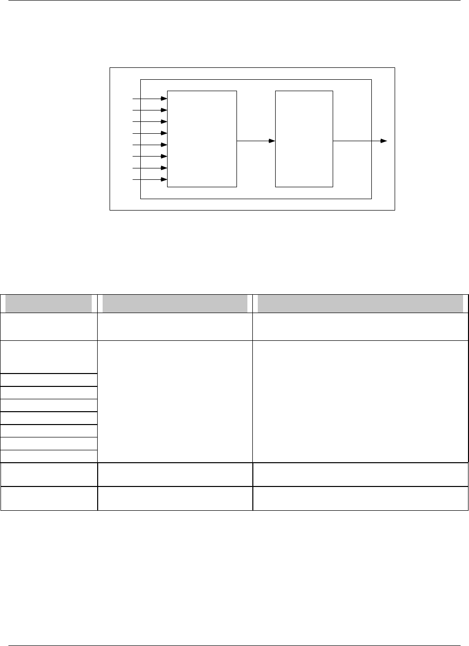
Logic
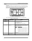
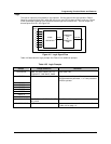
The input or inputs are processed by a logic operator. Call the result of this logic operation “Result”.
Result is a pulse that goes ON(1) when the logic is true, and OFF(0) when the logic is not true. Result
is then processed according to the specified condition type and condition time. The final output is a
discrete pulse CVn OS. See Figure 4-5.
LOGIC
OPERATOR
Inputs
A
B
C
D
E
F
G
H
Result
CONDITION
TYPE
&
CONDITION
TIME
CVn OS
Figure 4-5 Logic Signal Flow
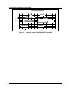
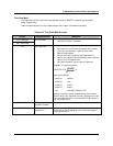
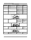
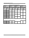
Table 4-25 describes the Logic prompts. See Table 4-2 for additional prompts.
Table 4-25 Logic Prompts
Prompt Range/Selections Definition
OPERATOR AND, OR, XOR, RESET/SET FF,
TOGGLE/FF, ONE SHOT, PASS
See Table 4-26.
INPUT A OFF, discrete parameter, 0, 1. Program at least 2 inputs. Only inputs
programmed with parameter, 1, or 0 are processed
with the operator.
INPUT B
INPUT C
INPUT D
INPUT E
INPUT F
INPUT G
INPUT H
CONDITION TYPE NONE, DELAY, EXTEND, PULSE,
RT PULSE
See Table 4-20 on page 111.
CONDITION TIME OFF or number Enter number of seconds of condition time. See
Table 4-20 on page 111.