


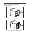

Installation
Video Recorder - User Manual 29
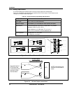
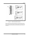
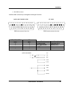
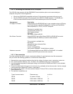
• With DB25 connector
Interface cable connectors pin arrangement and signal functions.
VIDEO RECORDER SIDE
DB25 male connector face view
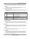
PC SIDE
DB25 female connector face view
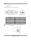
1 2 3 4 5 6 7 8 9 10 11 12 13
14 15 16 17 18 19 20 21 22 23 24 25
13 12 11 10 9 8 7 6 5 4 3 2 1
25 24 23 22 21 20 19 18 17 16 15 14
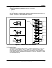
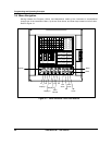
VIDEO RECORDER PC
Pin n° Pin n°
Direction Description
3 2 to video recorder transmitted DATA
2 3 from video recorder received DATA
- 4 from DTE request to send
- 5 to DTE clear to send
7 7 - ground
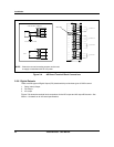
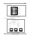
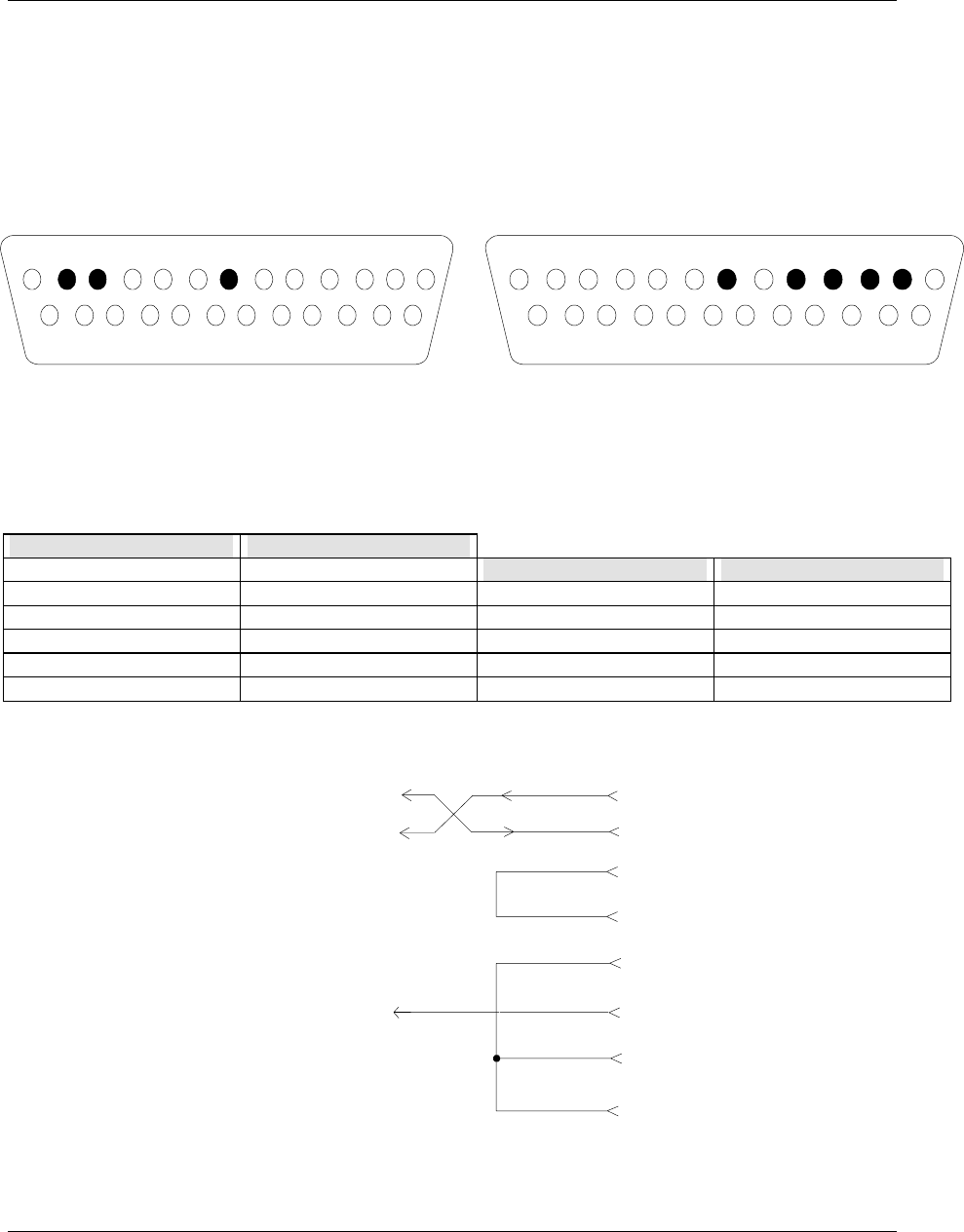
7
2 TD
3 RD
4 RTS
5 CTS
6 DSR
7 S.G.
8 DCD
20 DTR
VIDEO RECORDER
PC
2
3