


Programming Function Blocks and Features
Video Recorder – User Manual 96
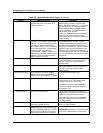
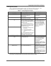
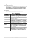
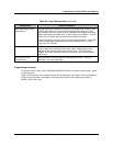
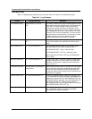
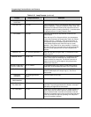
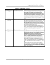
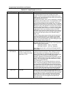
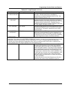
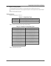
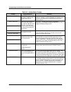
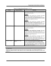
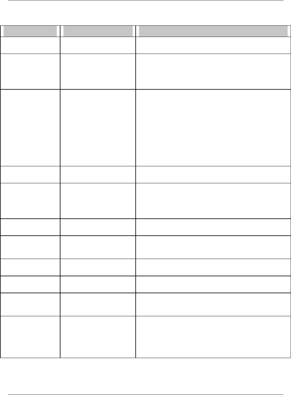
Table 4-10 Loop Prompts (continued)
Prompt Range/Selections Definition
IN DECIMAL
POSITION
Select decimal position Used for all input parameters of the loop.
INTERACTIVE YES, NO Select interactive (YES) or noninteractive (NO) for the control
algorithm operation. Interactive causes the Gain, Rate, and
Reset terms to interact to make up the proportional term of
the algorithm (similar to analog controllers). In noninteractive
the proportional term is simply related to Gain.
LATCHING YES, NO Select the desired action required after a failure to the
failsafe status.
When the loop’s PV or Set point #2 fails, the downstream
function block activates its failsafe (See Table 9-3, Default
condition column). If latching = YES, when the failure is
corrected the operator must take specific action to cancel
these failsafe measures and return the loop to normal
operation. (See Table 9-3 for action needed.) If latching =
NO, when the failure is corrected the loop will automatically
return to normal operation with no action needed by the
operator.
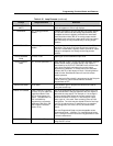
MANUAL OFF OFF, discrete parameter, 0,
1
When this discrete input goes ON (1) it causes the control
output to go off.
MANUAL RESET -100 to +100 This feature functions only when OFF is entered for RESET.
Enter a value equal to the desired loop output when the
process variable is at set point. This allows correction of
output to account for load changes to bring the process
variable up to set point.
OUTPUT LOW LIM &
OUTPUT HIGH LIM
OFF or number For cascade primary loop, set to PV LOW LIMIT and PV
HIGH LIMIT of the cascade secondary loop, respectively.
OUTPUT TRACKING 0-100%, Analog parameter,
OFF
This will be the loop's output value when the FORCE
REMOTE MAN input to the loop is high (1). See Force
Remote Man.
PROCESS
VARIABLE
OFF, analog parameter,
number
Process variable for the loop.
PROP BAND#1 &
PROP BAND#2
See GAIN#1 OR GAIN#2
PV LOW LIMIT &
PV HIGH LIMIT
OFF or number Enter the high and low limits for the process variable being
controlled. Loop tuning parameters are based on the span
selected by the high and low limit values.
PV TRACKING PV, OFF A selection of Process Variable (PV) will cause Set point #1
of the control loop to track the process variable when the
loop is in Manual mode. A transfer to Automatic mode will
maintain the tracked set point value as the working set point
of the loop unless the loop was operating from Set point 2
prior to the transfer to Manual.