


Diagnostic and error messages
Video Recorder – User Manual 255
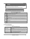
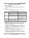
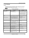
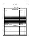
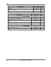
9.3 Error Messages
Overview
Sometimes errors occur while you are programming or loading a configuration into your instrument. In
most cases the instrument displays a descriptive error message. For example, if you try to program a
function block incorrectly, the instrument tells you the problem.
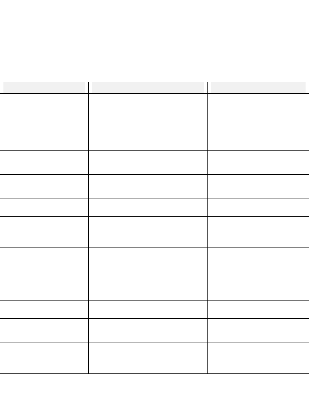
Table 9-4 lists these error messages along with a description of each one and what action to take.
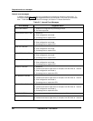
Table 9-4 Error Messages
Error Description User Action
Alarm/Event/Diagnostic burst
and transitions lost
The instrument had an
Alarm/Event/Diagnostic burst in the controller
and some transitions were lost.
Inspect the Alarm Summary/History
and the Discrete Summary Screen to
resolve any missing or unresolved
alarms vs their current states. If the
state transition that was missing was
an off state it will be matched and
processed upon the next on-off
transition of the corresponding alarm.
Block Phase Greater Than Block
Period
In Periodic Timer CV, the phase (start time)
is greater than the period. For example, the
start time is 8:00 and the period is 4:00.
Change Period to greater than phase
(Start Time) or change Start Time to
less than Period.
Channel Does Not Exist
A channel was loaded that does not exist.
For example, you loaded a dual loop
configuration into a single loop instrument.
Verify programming of affected
function block.
Circuit Limits Equal
Indirect circuit low/circuit high limits must be
unequal.
Change to unequal limits.
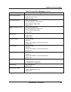
Condition Type Out of Range
Condition Type (Compare, Logic, Free form
Logic) is out of range. Probably caused by
someone incorrectly editing the configuration
file or by a corrupt .LNC file.
Verify programming of affected
function block.
Desired F0 Value Not
Programmed or Less Than Zero
In the F
0
Sterilization CV, desired F
0
is not
programmed or is less than zero.
Change F
0
value to greater than zero.
High Limit Outside of circuit
AI circuit high limit is > voltage limit of 5200
mV.
Change limit to within specified limits
for that type.
High Output Limit Greater than
20
A current output (CAT) high output limit
cannot be greater than 20
Decrease high limit.
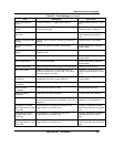
Hysteresis Less Than Zero
Alarm Hysteresis parameter should be
greater than or equal to zero.
Increase Hysteresis.
Impulse Time less than or Equal
to 0
Impulse time on a time
proportioning/duration adjusting output (DAT)
cannot be less than or equal to zero.
Increase impulse time.
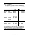
Incompatible Curve Type
AI is custom type, thermocouple class,
reference junction enabled but Y values are
not always increasing or not always
decreasing.
Reprogram curve so that for all n: Y
n
> Y
n+1
or Y
n
< Y
n+1