


Video Recorder – User Manual xi
Figures
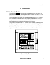
Figure 1-1 Video Recorder .............................................................................................................................. 1
Figure 1-2 Video Recorder Model Number ................................................................................................. 10
Figure 2-1 AI Board Terminal Block Connections...................................................................................... 22
Figure 2-2 10 ohm Copper Connections ..................................................................................................... 22
Figure 2-3 DI Board Terminal Block Connections...................................................................................... 23
Figure 2-4 AO Board Terminal Block Connections.................................................................................... 24
Figure 2-5 DO Board Terminal Block Connections .................................................................................... 25
Figure 2-6 DO Board Relay Contact Setting............................................................................................... 26
Figure 2-7 RS232 wiring configuration......................................................................................................... 29
Figure 2-8 RS422 wiring configuration ........................................................................................................ 30
Figure 2-9 RS422 Interface Connections.................................................................................................... 30
Figure 2-10 RS485 wiring configuration ........................................................................................................ 32
Figure 2-11 Interface connector ..................................................................................................................... 32
Figure 3-1 Video Recorder Front Door Buttons.......................................................................................... 36
Figure 3-2 Menu Navigation Guide Through ON LINE, PROGRAM, and MAINTENANCE mode
MAIN MENUs............................................................................................................................... 37
Figure 3-3 ON LINE mode MAIN MENU ...................................................................................................... 38
Figure 3-4 PROGRAM mode MAIN MENU.................................................................................................. 39
Figure 3-5 MAINTENANCE mode MAIN MENU ......................................................................................... 40
Figure 3-6 Connection of a keyboard or a barcode reader........................................................................ 47
Figure 3-7 Alarm 1 Function Block Components......................................................................................... 51
Figure 3-8 Example Input Parameter Connection....................................................................................... 55
Figure 3-9 Function Block Connection Format............................................................................................ 56
Figure 3-10 Example Configuration................................................................................................................ 59
Figure 3-11 Control Of Furnace Zone Temperature With 4-20 mA (CAT) Control Signal ..................... 60
Figure 3-12 Basic Function Blocks Required For Control Configuration Of Figure 3-11........................ 61
Figure 3-13 Labeling Each Function Block’s Name And Major Inputs And Outputs............................... 62
Figure 3-14 Labels For Internal Function Block Parameters...................................................................... 63
Figure 3-15 Interconnections Between Function Blocks............................................................................. 62
Figure 3-16 Complete Function Block Diagram Of Figure 3-11................................................................. 64
Figure 3-17 Control Of Wastewater pH Using A Time Proportioning (DAT) Control Signal .................. 65
Figure 3-18 Function Block Diagram Of Figure 3-17................................................................................... 65
Figure 3-19 Temperature Control Of Water Using Split Output Or Duplex Control ................................ 66
Figure 3-20 Function Block Diagram Of Figure 3-19................................................................................... 67
Figure 3-21 Temperature Control Of An Oil Heated Chemical Reaction Chamber ................................ 68
Figure 3-22 Function Block Diagram Of The Cascade Control Strategy.................................................. 69
Figure 3-23 Example Set Point Profile........................................................................................................... 70
Figure 3-24 Function Block Diagram Of Set Point Profile Control Of Figure 3-16 .................................. 71
Figure 3-25 Discrete Inputs Controlling Execution Of Set Point Profiler Function Block ....................... 71
Figure 3-26 Up To 16 Discrete Events May Be Programmed Per Step Of A Set Point Profile............. 72
Figure 3-27 Tying A Profile Function Block’s Discrete Events With Discrete Output Hardware ........... 73
Figure 3-28 Categories of Stored Data.......................................................................................................... 74
Figure 4-1 Function Block Configuration of a Typical Ratio Control Loop ....................................... 100
Figure 4-2 Compare Signal Flow...................................................................................................... 109
Figure 4-3 Compare’s Greater Than Result, With Hysteresis.......................................................... 110
Figure 4-4 Math CV Feedback Programming................................................................................... 114
Figure 4-5 Logic Signal Flow............................................................................................................ 116
Figure 4-6 Free Form Logic Signal Flow.......................................................................................... 119
Figure 4-7 Function Generator Curve .............................................................................................. 123